background image

discharge hole(s). Plan to position the unit approximately 2” aft of the front edge of the
compartment floor. This should allow about 4-6 inches of spacing from the aft bulkhead
to the back of the air conditioner. Once the air conditioner is removed, cut the required
hole(s) in the aft bulkhead.

Step 3: Preparation of the Baggage Compartment Floor

Remove the air conditioner and remove the aft baggage compartment floor. Note that the
condensate drain is on the aft right side of the unit. Determine the best routing of the
condensate drain hose to the Skybolt bulkhead drain fitting (AC-2125). The combination
of fittings should eliminate any chance of the hose kinking or any low spot between the
floor fitting (AN833-8D) and the skin bulkhead fitting. The approximate location of the
floor hole for the AN833-8D fitting should be determined based on positioning of the air
conditioner and the tie-down track.

Trace out the base of the air conditioner such
that it is approximately 2” aft of the front of
the floor (allow for clearance of the
protective lip) and in the center.

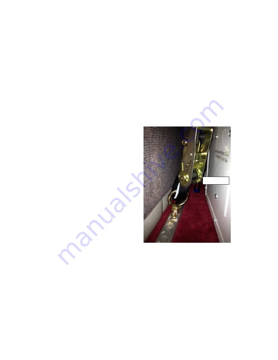
Now determine the location for both tie-
down tracks. Plan on approximately 1”
clearance from the edge of the track to the
side of the floor in order to have access to
the floor hold-down screws. Run the track
parallel to the cabin wall (floor edge). This
will maximize the clearance for the tie down
ratchets (AC-2128). Before committing to
the exact location of the tracks, check that
the backing strip is clear of any airframe
structure beneath the floor.

Based on the location of the tracks, now
determine a more precise location of the
primary wire cannon plughole, the controller
cable hole, and the condensate drain hole. Allow as much clearance as possible away
from the estimated location of the tie-down ratchets.

Drill all necessary holes for the cannon plug, controller cable and drain fitting. Note that
the cannon plug mounting screw holes are close to the body of the plug, thus, drill this
hole only big enough to mount the plug and no more.
Drill 4 each plug socket mounting holes. You may find it easier to solder the primary and
ground #6 wires before mounting the plug socket to the floor.

Locate each hole in the carpet so that holes can be cut in the carpet.

Drain Fitting

Summary of Contents for Artic Air 24

Page 1: ...AC 2109 to be installed with the circuit breaker For the Beech Baron the easiest routing is along the right side of the fuselage and cabin to the aft baggage area This routing requires the least amount of side panels or floor removal When routing the primary wire also plan to route the controller cable The controller cable is shielded and should not be cut or spliced We recommend a longer control ...

Page 2: ...ggage compartment floor Before installing the plug complete step 3 Preparation of the Baggage Compartment Floor Once the plug is installed the floor is basically attached to the airframe to the limit of the extra length wire allowed in your installation If you tackled the primary wire as the first step in installation before drilling the connecter hole and the controller cable hole and soldering t...

Page 3: ...arance of the protective lip and in the center Now determine the location for both tie down tracks Plan on approximately 1 clearance from the edge of the track to the side of the floor in order to have access to the floor hold down screws Run the track parallel to the cabin wall floor edge This will maximize the clearance for the tie down ratchets AC 2128 Before committing to the exact location of...

Page 4: ...fitting such that the drain mast chamfer is facing aft We use an Oring on the outer surface and use LocTite Red to secure the fitting nut Before you attach the hose from the belly fitting to the floor fitting solder and install the cannon plug Step 5 Final Installation of Cannon Plug Route the primary wire through the floor Properly assemble the plug socket components including the heat shrink ont...

Page 5: ...fety wire the vinyl hose end to the fitting Note For air conditional removal simply loosen and disconnect the fitting Step 8 Controller Location and Installation This step will be unique to every aircraft based on panel availability The key is to have plenty of controller cable length We recommend at least 20 35 feet maximum feet as any shorter length may restrict your options Step 9 Ground Use On...

Page 6: ......

Page 7: ......

Page 8: ......

Page 9: ......

Page 10: ......

Page 11: ......

Page 12: ......

Page 13: ......

Page 14: ......

Page 15: ......

Page 16: ......

Page 17: ......

Page 18: ......

Page 19: ......

Page 20: ......

Page 21: ......

Page 22: ......

Page 23: ......

Reviews: