5
INSTALLATION AND CONNECTION
Warning!
⚫
Sustained exposure to high humidity during storage may cause damage to
electronics and reduce the lifetime of the equipment.
We recommend that storage humidity shall not exceed 50% relative humidity.
Once the MiCOM products have been unpacked, we recommend that they are
energized within the three following months.
Where electrical equipment is being installed, sufficient time should be
allowed for acclimatization to the ambient temperature of the environment,
before energization.
Warning!
⚫
Only qualified personnel, familiar with the “Warning” page at the beginning of
this manual, may work on or operate this device.
Warning!
⚫
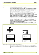
Operational Grounding”) should be noted. In particular, check that the
protective ground connection is secured with a tooth lock washer, as per the
diagram “Installing the protective grounding conductor terminal” (
If a cable screen is added to this connection or removed from it, then the
protective grounding should be checked again.
Warning!
⚫
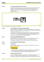
The SC connector and RJ45 wire of the Ethernet module cannot be connected
at the same time.
Warning!
⚫
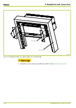
Installation of the detachable HMI: A protective conductor (protective
earth) with a cross section at least 1.5 mm² (US:
AWG14 or thicker) must be
connected to the protective grounding conductor terminal on the detachable
HMI at one end and on the other end to the protective grounding conductor
terminal on the device’s case. Both the detachable HMI and the device have to
be installed in the same substation.
In order to prevent personal injuries the communications cable installed to the
detachable HMI must never come in contact with parts that may be subjected
to dangerous live voltages.
It is prohibited to install or run the communications cable to the detachable
HMI next to high-voltage lines or high-voltage connections. This is to prevent
induced currents that would lead to electromagnetic interferences.
P631
P631/EN M/R-11-C // P631-310-650
5-1
Summary of Contents for P631
Page 2: ......
Page 4: ......
Page 7: ...Changes after going to press...
Page 8: ......
Page 16: ...P631 Table of Contents 8 P631 EN M R 11 C P631 310 650...
Page 56: ...P631 2 Technical Data 2 28 P631 EN M R 11 C P631 310 650...
Page 236: ...P631 3 Operation 3 180 P631 EN M R 11 C P631 310 650...
Page 246: ...P631 4 Design 4 10 P631 EN M R 11 C P631 310 650...
Page 266: ...P631 5 Installation and Connection 5 20 P631 EN M R 11 C P631 310 650...
Page 276: ...6 8 Configurable Function Keys P631 6 Local Control HMI 6 10 P631 EN M R 11 C P631 310 650...
Page 548: ...P631 10 Commissioning 10 10 P631 EN M R 11 C P631 310 650...
Page 568: ...P631 12 Maintenance 12 8 P631 EN M R 11 C P631 310 650...
Page 570: ...P631 13 Storage 13 2 P631 EN M R 11 C P631 310 650...
Page 572: ...P631 14 Accessories and Spare Parts 14 2 P631 EN M R 11 C P631 310 650...
Page 576: ...P631 15 Order Information 15 4 P631 EN M R 11 C P631 310 650...
Page 582: ...P631 A2 Internal Signals A2 4 P631 EN M R 11 C P631 310 650...
Page 608: ...P631 A4 Telecontrol Interfaces A4 18 P631 EN M R 11 C P631 310 650...
Page 637: ......

