3.30
Programmable Logic (Function Groups LOGIC and LOG_2)
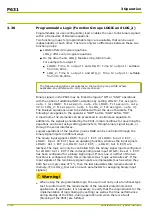
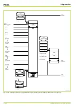
Programmable (or user-configurable) logic enables the user to link binary signals
within a framework of Boolean equations.
Two function groups for programmable logic are available, that can be used
independently of each other. There are only two differences between these two
function groups:
●
LOGIC offers 32 logical equations.
LOG_2 offers only 4 logical equations.
●
On the other hand, LOG_2 features long-term timers.
For example for output 1:
■
LOGIC: Time t1 output 1 and LOGIC: Time t2 output 1: settable
from 0 to 600 s.
■
LOG_2: Time t1 output 1 and LOG_2: Time t2 output 1: settable
from 0 to 60,000 s.
The following description concentrates on the function group LOGIC. Where
applicable, any differences to LOG_2 are mentioned.
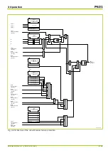
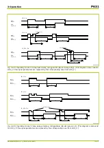
Binary signals in the P631 may be linked by logical “OR” or “AND” operations
with the option of additional NOT operations by setting LOGIC: Fct.assignm.
outp. 1 (or LOGIC: Fct.assignm. outp. 2 to LOGIC: Fct.assignm. outp.
32, or LOG_2: Fct.assignm. outp. 1 to LOG_2: Fct.assignm. outp. 4).
The Boolean equations need to be defined without the use of brackets. The
following rule applies to the operators: “NOT” before “AND” before “OR”.
A maximum of 32 elements can be processed in one Boolean equation. In
addition to the signals generated by the P631, initial conditions for governing the
equations can be set using setting parameters, through binary signal inputs, or
through the serial interfaces.
Logical operations of the function group LOGIC can be controlled through the
binary signal inputs in different ways.
The binary input signals LOGIC: Input 1 EXT (or LOGIC: Input 2 EXT, …,
LOGIC: Input 40 EXT) have an updating function, whereas the input signals
LOGIC: Set 1 EXT (or LOGIC: Set 2 EXT, …, LOGIC: Set 8 EXT) are
latched. The logic can only be controlled from the binary signal inputs configured
for LOGIC: Set 1 EXT if the corresponding reset input LOGIC: Reset 1 EXT)
has been configured for a binary signal input. If only one or neither of the two
functions is configured, then this is interpreted as “Logic externally set”. If the
input signals of the two binary signal inputs are implausible (such as when they
both have a logic value of “1”), then the last plausible state remains stored in
memory. (For LOG_2, there are no such parameters for assigning binary input
signals.)
Warning!
⚫
When using the programmable logic, the user must carry out a functional type
test to conform with the requirements of the relevant protection/control
application. In particular, it is necessary to verify that the requirements for the
implementation of logic linking (by setting) as well as the time performance
during startup of the P631, during operation and when there is a fault
(blocking of the P631) are fulfilled.
P631
3 Operation
3-172
P631/EN M/R-11-C // P631-310-650
Summary of Contents for P631
Page 2: ......
Page 4: ......
Page 7: ...Changes after going to press...
Page 8: ......
Page 16: ...P631 Table of Contents 8 P631 EN M R 11 C P631 310 650...
Page 56: ...P631 2 Technical Data 2 28 P631 EN M R 11 C P631 310 650...
Page 236: ...P631 3 Operation 3 180 P631 EN M R 11 C P631 310 650...
Page 246: ...P631 4 Design 4 10 P631 EN M R 11 C P631 310 650...
Page 266: ...P631 5 Installation and Connection 5 20 P631 EN M R 11 C P631 310 650...
Page 276: ...6 8 Configurable Function Keys P631 6 Local Control HMI 6 10 P631 EN M R 11 C P631 310 650...
Page 548: ...P631 10 Commissioning 10 10 P631 EN M R 11 C P631 310 650...
Page 568: ...P631 12 Maintenance 12 8 P631 EN M R 11 C P631 310 650...
Page 570: ...P631 13 Storage 13 2 P631 EN M R 11 C P631 310 650...
Page 572: ...P631 14 Accessories and Spare Parts 14 2 P631 EN M R 11 C P631 310 650...
Page 576: ...P631 15 Order Information 15 4 P631 EN M R 11 C P631 310 650...
Page 582: ...P631 A2 Internal Signals A2 4 P631 EN M R 11 C P631 310 650...
Page 608: ...P631 A4 Telecontrol Interfaces A4 18 P631 EN M R 11 C P631 310 650...
Page 637: ......

