RedEdge-
MX
Integration Guide Rev 01
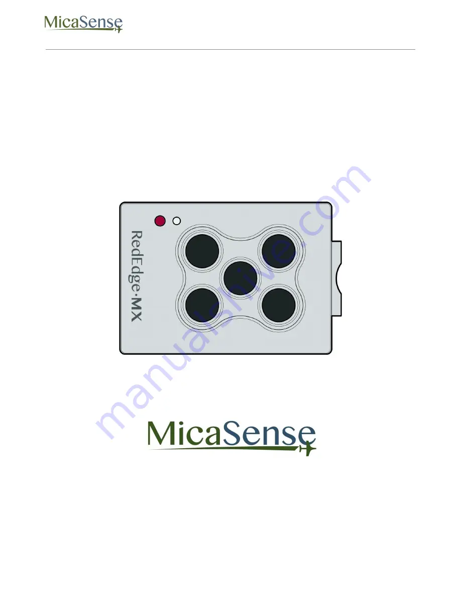
MicaSense RedEdge-MX
TM
Multispectral Camera
Integration Guide
Revision: 01 – October 2018
MicaSense, Inc.
Seattle, WA
© 2018 MicaSense, Inc. Page 1 of 19
Page 1: ...RedEdge MX Integration Guide Rev 01 MicaSense RedEdge MX TM Multispectral Camera Integration Guide Revision 01 October 2018 MicaSense Inc Seattle WA 2018 MicaSense Inc Page 1 of 19...
Page 2: ...puts 6 External Power and External Trigger PWR TRG 6 Downwelling Light Sensor 2 DLS 2 9 Serial and Ethernet Data COMM 10 Example Integrations 11 Standalone Integration Using Camera DLS GPS Module 11 I...
Page 3: ...and Scope This document provides the information required for mechanical and electrical integration of a MicaSense RedEdge MX multispectral camera onto a host aircraft 2 Camera Dimensions and Mass Al...
Page 4: ...edEdge MX camera can be attached to the host aircraft using at least 2 of the 4 provided threaded mounting points It is important to use threaded points opposite of each other M3x0 5 screws are used f...
Page 5: ...er technology the camera is able to withstand some vibration without degrading image quality nevertheless vibration isolation between the camera mounting platform and the aircraft is recommended Use o...
Page 6: ...al Power and External Trigger PWR TRG Signal definitions and connector Pin Signal 1 Trigger 2 Ground 3 Power Connector on Camera Hirose DF13A 3P 1 25H 51 Mating Connector Hirose DF13 3S 1 25C 28AWG wi...
Page 7: ...the specified input voltage range may result in unreliable operation or damage to the camera The RedEdge MX contains under voltage and over voltage protection circuitry which nominally applies at 3 8...
Page 8: ...iple grounds are used for power and trigger of the camera Only one ground should be connected to the camera typically this is the ground that corresponds to the source of the power If the ground of th...
Page 9: ...a of the TIFF images captured by the camera This information can then be used by specialized processing tools like Pix4Dmapper to correct for global lighting changes in the middle of a flight such as...
Page 10: ...RedEdge MX Integration Guide Rev 01 Measurements and Attachment Points Height 14 03 mm Width 46 00 mm Length 63 50 mm Weight 49 g 2018 MicaSense Inc Page 10 of 19...
Page 11: ...signals on RedEdge MX The signal types are outlined in the Sensor Firmware Guide The camera trigger button will command a capture on the RedEdge MX This is useful for capturing a preflight image of t...
Page 12: ...tilized for geotagging of the RedEdge MX imagery if system GPS signals are not provided to the sensor by other means Install the module where it will have a clear view of the sky far away from any dev...
Page 13: ...Data COMM This connector is available for tighter integration with host aircraft It includes a standard TTL level serial port as well as an Ethernet port Documentation for the communications protocol...
Page 14: ...hat power is provided to the RedEdge MX system Triggering is configured via the WiFi interface to either Overlap or Timer mode GPS information is provided by the included GPS receiver connected to the...
Page 15: ...h must be calculated in a flight planner using the sensor s field of view to create an appropriate row spacing We recommend this mode because it helps ensure proper overlap 75 or higher which is essen...
Page 16: ...eed to configure the camera for operation over WiFi at the start of each operation In this integration triggering can be commanded via a rising edge pulse falling edge pulse or most commonly using a P...
Page 17: ...erial or Ethernet interface Host integration through serial connection is accomplished through MAVLink messaging and is compatible with common autopilot systems such as Pixhawk and APM Deep integratio...
Page 18: ...available for use in any of the integration scenarios listed above though typically the aircraft will be providing both triggering as well as GPS IMU information to the camera via serial Ethernet pro...
Page 19: ...Seattle WA 98103 The contents of this guide are subject to change without notice MicaSense Inc assumes no liability for incidental or consequential damages arising from the use of this product and any...