RedEdge 3 User Manual Rev 06
© 2015 MicaSense, Inc. Page 1 of 33
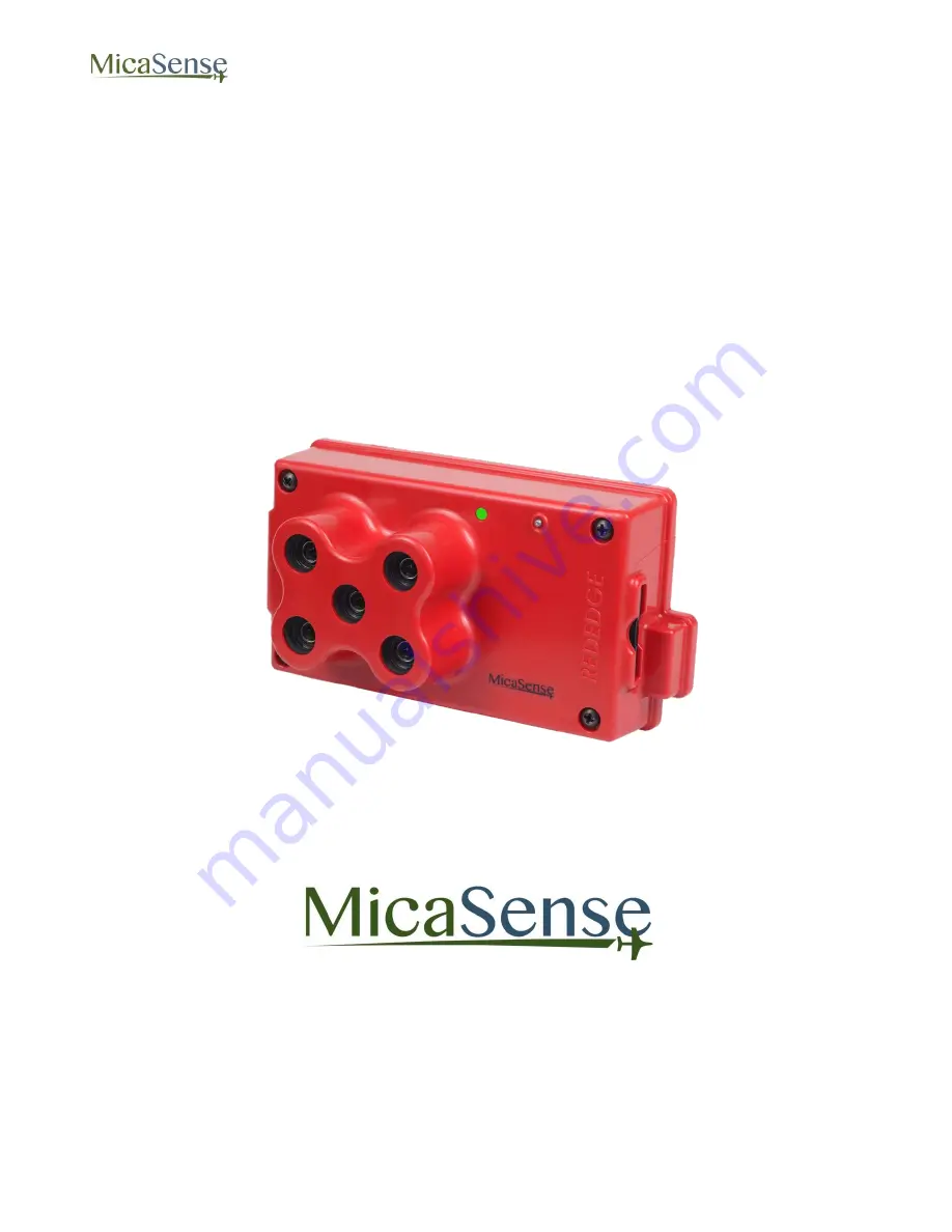
MicaSense RedEdge
™ 3
Multispectral Camera
User Manual
Rev 06
– October 2015
MicaSense, Inc.
Seattle, WA
Page 1: ...RedEdge 3 User Manual Rev 06 2015 MicaSense Inc Page 1 of 33 MicaSense RedEdge 3 Multispectral Camera User Manual Rev 06 October 2015 MicaSense Inc Seattle WA...
Page 2: ...VIEW 9 3 1 ESTABLISHING WIFI CONNECTION 9 3 2 HOME PAGE 10 3 3 LIVE VIEW PAGE 11 3 4 COVERAGE PAGE 13 3 5 SETTINGS PAGE 17 3 5 1 TIMER MODE 18 3 5 2 EXTERNAL TRIGGER MODE 19 3 5 3 OVERLAP MODE 20 3 5...
Page 3: ...EPLACEMENT PRODUCT COSTS ARISING OUT OF THE PURCHASE USE OR PERFORMANCE OF THE REDEDGE CAMERA UNDER ANY THEORY OF LIABILITY EVEN IF MICASENSE HAS BEEN ADVISED OF THE POSSIBILITY OF SUCH DAMAGES MICASE...
Page 4: ...3 Overview The MicaSense RedEdge 3 is a professional multispectral camera capable of simultaneous capture of five discrete spectral bands to generate precise and quantitative information on the vigor...
Page 5: ...cards are not compatible with the RedEdge camera Connect GPS Module If stand alone GPS module is used o Connect one end of 6 pin cable to camera connector labeled GPS o Connect other end of 6 pin cabl...
Page 6: ...or pinout Connect power cable to connector labeled PWR TRIG To remove connector do not pull on wires instead use a small flathead screwdriver to pry out the connector See Section 5 CAUTION Power must...
Page 7: ...The camera will automatically turn ON when power is first applied to the external power connector If the camera is manually turned OFF it can be re powered ON by pressing the ON OFF button Status LED...
Page 8: ...Always power OFF the camera before removing the SD card Failure to do so may corrupt some of the files in the SD card Capturing Images Manual Trigger With the camera turned ON and SD card installed pr...
Page 9: ...a connection with the camera To establish the WiFi connection 1 Turn on the camera and wait for initialization process to complete 2 Use the device s WiFi configuration method to search for a WiFi acc...
Page 10: ...RedEdge 3 User Manual Rev 06 2015 MicaSense Inc Page 10 of 33 3 2 Home Page Provides status information for the camera and the GPS receiver that is connected to it Figure 2 Home Page...
Page 11: ...RedEdge 3 User Manual Rev 06 2015 MicaSense Inc Page 11 of 33 3 3 Live View Page Provides a live preview of images captured with the camera Figure 3 Live View Page Figure 4 Imager Nomenclature...
Page 12: ...The Capture button forces a capture for the camera and is equivalent to pressing the manual trigger button on the camera Streaming The Streaming checkbox is used for near real time preview images fro...
Page 13: ...ation Figure 5 Coverage Page Clicking the captures kmz link will cause the camera to generate a KMZ file that will be downloaded by your browser The KMZ file contains the lat lon alt of all captures i...
Page 14: ...current estimation settings Camera Orientation indicates the directionality of the camera with respect to the aircraft as shown below Figure 7 Landscape Orientation on Left Portrait Orientation on Ri...
Page 15: ...modern smart phone Finally you will be presented with an estimate of your coverage Any area that is dark green has a high probability of correctly being processed in ATLAS Areas that are yellow may wo...
Page 16: ...erage map shown above double check to make sure the Flight AGL is set correctly If the Flight AGL is incorrect click back on the Flight Adjustment section correct the Flight AGL then click on Draw Cov...
Page 17: ...c Page 17 of 33 3 5 Settings Page The settings page is used primarily to configure the Auto Capture options for the camera The camera supports three methods of Auto Capture Timer mode External Trigger...
Page 18: ...camera will capture as quickly as it can about once a second 3 Press the Save button to save the Timer mode settings 4 Press the Start button to begin capturing images at the desired interval rate 5...
Page 19: ...l trigger on the rising edge of a pulse Falling Edge Camera will trigger on the falling edge of a pulse Short PWM Camera will trigger if PWM transitions from longer than Threshold to shorter than Thre...
Page 20: ...ed as AGL Above Ground Level altitude 3 Specify the Along Track Overlap in of image that is common between one image and the adjacent one 4 Press the Save button to confirm the settings 5 When the air...
Page 21: ...nced Configuration You can specify the RAW Format to be either 12 bit DNG or 16 bit TIFF The 12 bit DNG format will produce files that are 25 smaller in size than 16 bit TIFF files The menu also enabl...
Page 22: ...hanging the camera s network mode you must click Save and then reboot the camera in order of the new setting to take effect Ethernet Configuration allows you to assign a different IP address to the ca...
Page 23: ...ning the following information may be required Item Value Lens Focal Length 5 5 mm Lens Field of View 47 2 deg HFOV Imager Size 4 8 mm x 3 6 mm Imager Resolution 1280 x 960 pixels Figure 16 shows para...
Page 24: ...for details on connectors pin outs and voltage specifications When removing the cables that plug into these connectors use a small flathead screwdriver to pry off the connector at the plastic interfa...
Page 25: ...001 for instance Two log files are also created Within each subfolder a group of 5 files is created for each image capture 5 TIFF files The suffix at the end of each file indicates the imager number...
Page 26: ...hould be verified prior to flight 2 A minimum cross track and along track overlap of at least 75 is recommended Figure 19 Overlap Recommendations 3 At least one track of the flight area should be outs...
Page 27: ...the angle of view from the camera to the panel is as perpendicular as possible without shadowing Avoid having the sun reflect off any surface and hit the panel It s best to place your shadow just to t...
Page 28: ...t illumination avoid days with clouds that move in and out and cast changing shadows on the ground 7 For best results data collection should be done within 2 5 hours of local solar noon 8 For vineyard...
Page 29: ...4 0 to 5 5 V DC Verify free space on SD card sufficient for mission Verify GPS date and time are correct Wait for GPS fix Confirm GPS fix 3 Satellites Used Confirm green blinking Status LED Configure...
Page 30: ...ger mode Force a manual trigger capture using aircraft s controller In Live View Page verify image captured 5 After Flight Connect to camera using WiFi capable device In Home Page verify SD card free...
Page 31: ...he back of the camera will immediately start to rapidly flash indicating that the camera is installing the firmware When the red light stops flashing the installation process is complete should be les...
Page 32: ...1 8 Power 5 0 V DC 4 W nominal Spectral Bands Narrowband Blue Green Red Red Edge Near IR Ground Sample Distance 8 2 cm pixel per band at 120 m 400 ft AGL Capture Speed 1 capture per second all bands 1...
Page 33: ...ST Seattle WA 98103 The contents of this manual are subject to change without notice MicaSense Inc assumes no liability for incidental or consequential damages arising from the use of this product and...