8 |
P a g e
Solar Monitor -
ISO
SNMP
Mi
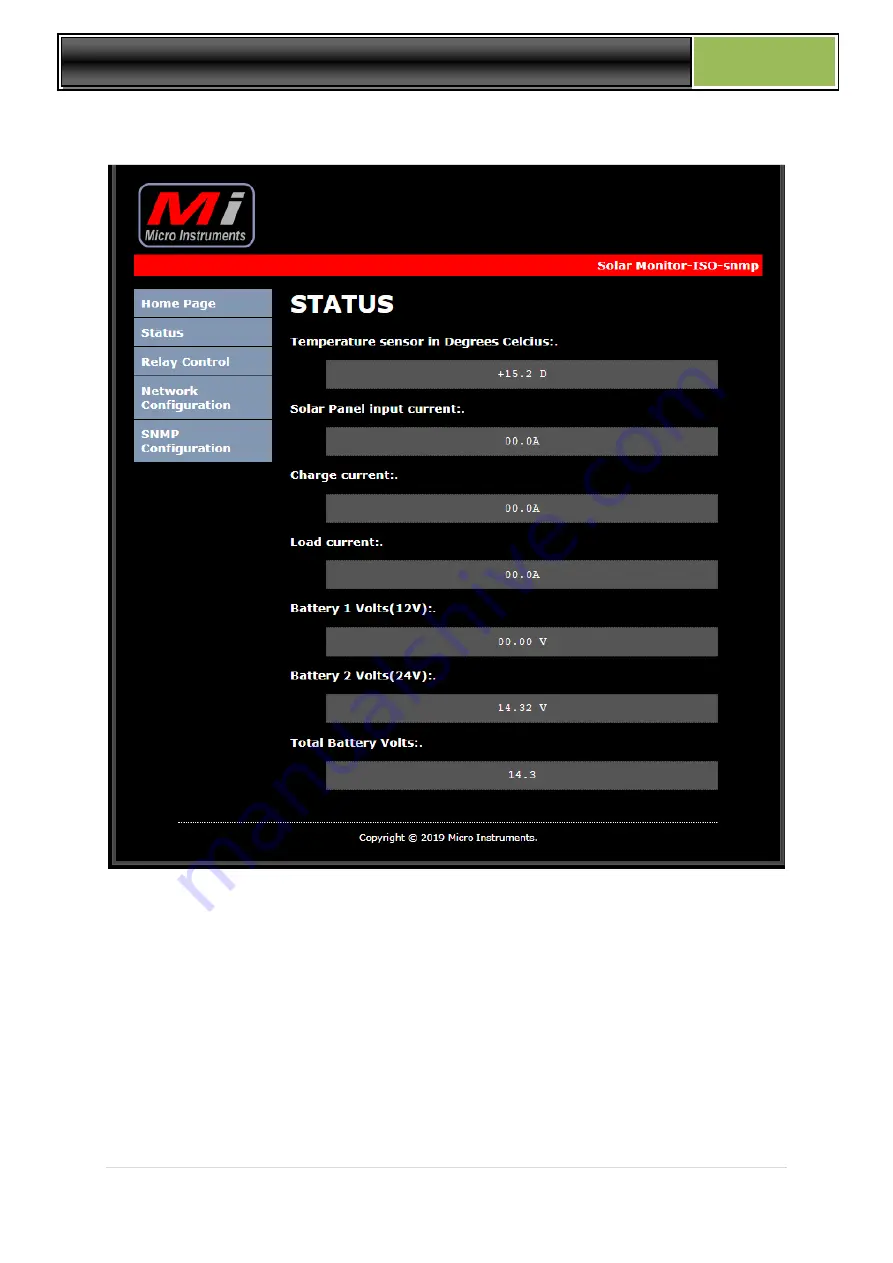
STATUS PAGE
Temperature sensor is displayed in degrees Celsius.
Solar panel input current
Charge current
Load current
Battery 1 voltage
Battery 2 voltage (24V system )
Total battery voltage
Page 1: ...s for 12V and 24V Battery systems With Optional external relay module INDEX 1 SYSTEM DESCRIPTION 2 SYSTEM CONNECTIONS 3 RESET TO DEFAULTS AND PASSWORDS 4 OPTIONAL 5 WAY RELAY MODULE 5 WEB PAGES 6 TFTP...
Page 2: ...m changes any existing solar regulator into a smart monitoring device Solar Panel input current Battery charge current Load current battery voltage and temperature data is available via embedded web p...
Page 3: ...al voltage for a 24V system if the 12V centre tap wire is connected see system connections page Solar Panel voltage not monitored Some Solar Regulators are common negative regulators where the positiv...
Page 4: ...4 P a g e Solar Monitor ISO SNMP Mi 2 SYSTEM CONNECTIONS USING LOAD OUTPUT FROM REGULATOR SYSTEM CONNECTIONS NO LOAD OUTPUT USED FROM REGULATOR...
Page 5: ...nected to a 24V battery system the centre tap blue wire in drawing have to be connected IMPORTANT NOTE The Alarm input is a potential free contact input only and NO voltages should be injected here Pe...
Page 6: ...itor via a 10way ribbon cable supplied with the relay module Relay s is rated at 10Amps 220Vac Relay 1 2 3 can only be toggled to activate for 10sec then return to the off position again and is used t...
Page 7: ...the status of Relays 5 to 1 is given and indicated by a green dot if the relay is active powered A module heartbeat indication by a yellow dot flashes once per second as the software runs through the...
Page 8: ...olar Monitor ISO SNMP Mi STATUS PAGE Temperature sensor is displayed in degrees Celsius Solar panel input current Charge current Load current Battery 1 voltage Battery 2 voltage 24V system Total batte...
Page 9: ...toggled for 10 second periods and is typically used to reset radios or routers without logging yourself out completely from the remote site after a relay was accidently switched relay 1 to 3 will ret...
Page 10: ...ly be left unaltered NETWORK CONFIGURATION PAGE MAC address is displayed and cannot be changed Setup IP address Gateway and Subnet Mask and user password After the configuration was saved the Reboot i...
Page 11: ...ger software OID table number of services 11 1 3 6 1 4 1 45501 1 3 1 0 Relay 4 status integer 0 off 1 on 1 3 6 1 4 1 45501 1 3 2 0 Relay 5 status integer 0 off 1 on 1 3 6 1 4 1 45501 1 3 3 0 Total Bat...
Page 12: ...ng the equipment to indicate online offline status Graphing each device added will have its own graphical presentation of all measured data and is unit specific Email alerts Multiple email addresses c...
Page 13: ...t consumption with LAN port active 110mA 12Vdc 50mA 24Vdc Current sensors on Charge Load and Solar panel 75 Amp isolated non invasive current sensors 9mm OD cables max current sensors accept 9mm cable...