Mi-T-M
Undercarriage Wash System Operator's Manual
9
INSTALLATION
INSTALLATION:
1. Place pump skid and holding tank on level concrete surface in an enclosed
area preferably with floor drain. Place holding tank within a few feet of pump
close enough to allow 5’ supply hose to reach. Level pump as needed with
feet levelers and anchor to concrete if desired. Do not allow pump or tank to
be exposed to freezing temperatures.
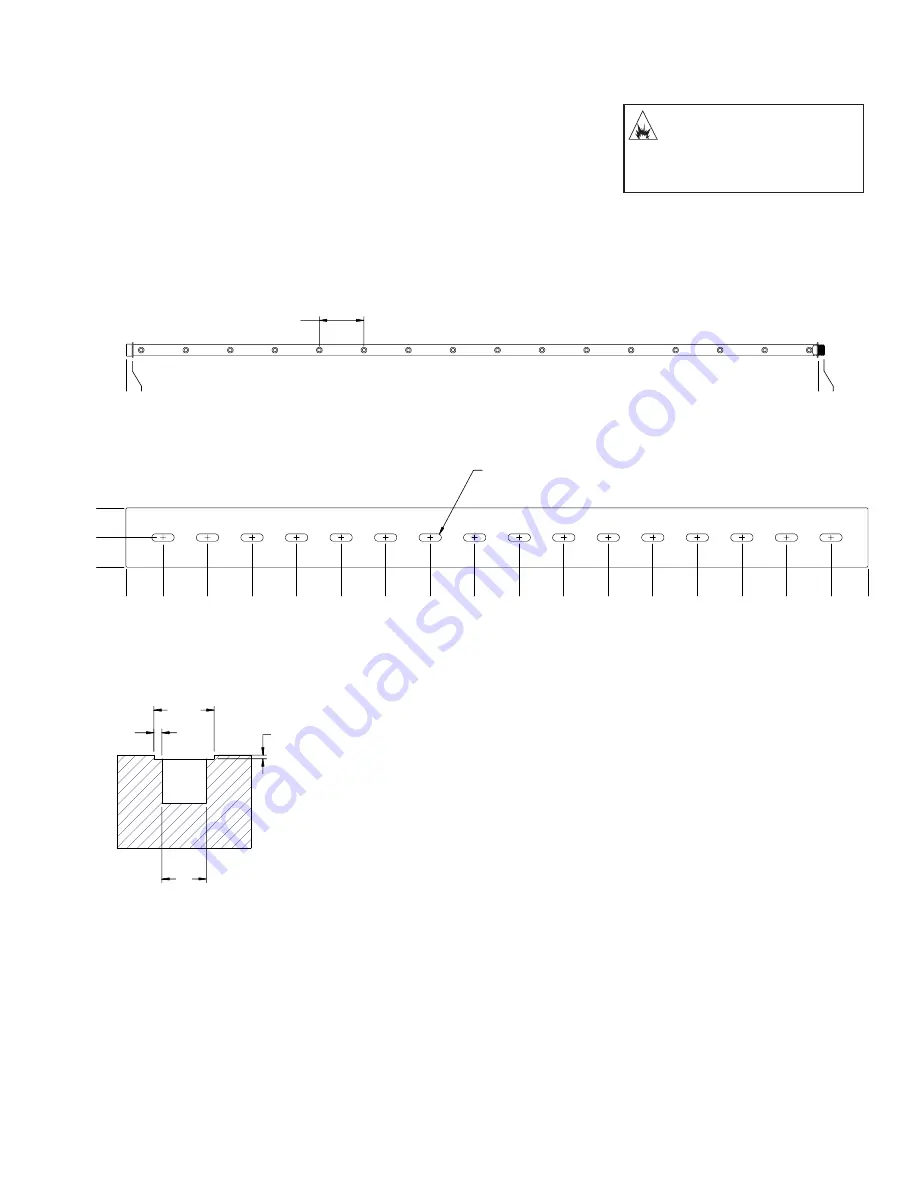
2. Place spray bar inside concrete trench, nozzles about 1” below the concrete
surface. Level and Anchor into place- allow enough room for connection hose
or piping to connect to spray bar. Do not allow spray bar to be exposed to
freezing temperatures.
NOTE: Trench will accumulate water and dirt so a drain line needs to be
installed to wash bay main trench or drain line.
Figure 1: Spray Bar dimensions and nozzle spacing
Figure 2: Cover dimensions
Figure 3: Trench minimum dimensions for spray bar and cover installation.
3. Place Cover over spray bar on lip of concrete trench. Center slots over nozzles.
4. Install selector switch remote box and photo-eye to wash-bay wall in front of
undercarriage trench. Photo-eye will reach a maximum of 10’, so it needs to
be placed within this distance of the equipment or vehicles moving by. Place
far enough in front spray bar to avoid water spraying photo-eye or remote
box at least 10 ft. is recommended.
DANGER RISK OF UNIT
BURSTING! DO NOT
STORE/OPERATE
UNIT IN FREEZING
ENVIRONMENTS!
0
3/4
93 1/4
(94)
6 TYP.
SPRAY BAR DIMENSIONS
1 X 3.000 LONG SLOT
(16) PLACES
0
4
8
0
5
11
17
23
29
35
41
47
53
59
65
71
77
83
89
95
100
SPRAY BAR COVER DIMENSIONS
1 1/16
6
8 1/8
1/2
TRENCH MINIMUM
DIMENSIONS


