


20301763
39
DVBL7 Series Gas Fireplace
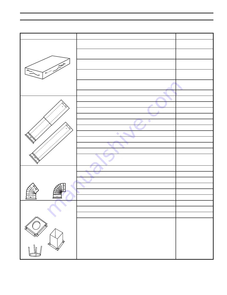
VentInG coMponentS
Description
Model number
Vertical Vent Termination Kits
Vertical Vent Termination w/ Storm Collar
47TLVTK
(flashing NOT included)
Vertical Vent Termination w/ Storm Collar - 8 pack
47TLVTK/8
(flashing NOT included)
Vertical Vent Termination w/ 1/12 - 6/12 Flashing, Storm
47TLVTKA
Collar and Ceiling Support Kit
Vertical Vent Termination w/ 6/12 - 12/12 Flashing,
47TLVTK8
Storm Collar and Ceiling Support Kit
Vertical Vent Termination w/ Flat Flashing, Storm Collar
47TLVTKC
and Ceiling Support Kit
T-Lock Pipe
30" Flex Pipe - single pack
7FDVP30
12" - 18" Adjustable Vent Length
47TL1218
35" - 64" Adjustable Vent Length
47TL3564
8" Vent Pipe - 4 pack
47TL8/4
12" Vent Pipe - 4 pack
47TL12/4
24" Vent Pipe - 4 pack
47TL24/4
36" Vent Pipe
47TL36
36" Vent Pipe - 30 pack
47TL36/30
48" Vent Pipe
47TL48
48" Vent Pipe - 30 pack
47TL48/30
T-Lock Elbows
45° Elbow for Vertical/Horizontal Offset
47TLE45
45° Elbow for Vertical Offsets - 8 pack
47TLE45/8
90° Elbow for Vertical/Horizontal Offset
47TLE90
90° Elbow for Vertical/Horizontal Offset - 8 pack
47TLE90/8
Shields and Supports
1" Firestop
7DV1FS
1" Attic Insulation Shield
7DV1AIS
Combination Horizontal Offset/Roof Support
7DVCS
584B
Vent components
Starter Kit
2/25/99 djt
584E
Venting Components
Telescope vent
2/25/99 djt
10/20/99 twist lock
3/10/10 T-lock
584F
Venting Components
Pipe sections
2/25/99 djt
10/20/99 twist lock
3/10/10 T-lock
584D
Vent Components
90 degree elbow
2/25/99 djt
10/20/99 twist lock
3/10/10 T-lock
584C
Vent components
45 degree elbow
2/25/99 djt
10/20/99 twistlock
3/10/10 T-lock
584G
Venting Components
Firestop spacer
2/25/99 djt
584H
Venting components
attic insulation shield
2/25/99 djt
584I
vent components
offset support
2/25/99 djt
VertIcaL VentInG