MHSC 400DVBLNV7CE Installation And Operating Instructions Manual Download Page 14

20301763

14

DVBL7 Series Gas Fireplace

VentInG InStaLLatIon InForMatIon

how to uSe the Vent Graph

The  Vent  Graph  should  be  read  in  conjunction  with  the 
following vent installation instructions to determine the re-
lationship between the vertical and horizontal dimensions 
of the vent system.
1.  Determine  the  height  of  the  center  of  the  horizontal 

vent pipe exiting through the outer wall.  Using this di-
mension on the Sidewall Vent Graph, 

Figure 12

, locate 

the point intersecting with the slanted graph line. 

2.  From the point of this intersection, draw a vertical line 

to the bottom of the graph.

3.  Select the indicated dimension, and position the fire-

place in accordance with same. 

exaMpLe a:


If the vertical dimension from the floor of the unit is 11’ (3.4 
m) the horizontal run to the face of the outer wall must not 
exceed 14’ (4.3 m).

exaMpLe B:


If the vertical dimension from the floor of the unit is 7’ (2.1 
m), the horizontal run to the face of the outer wall must not 
exceed 7’ (2.1 m).

refer to 

Page 18

 for requirements for snorkels.

FP2337a
sidewall vent graph

2    4    6   8  10  12 14  16 18  20

40
38
36
34
32
30
28
26
24
22
20
18
16
14
12
10

8
6
4
2

.60 1.2 1.8

6.1

5.5

4.9

4.3

3.7

3.0

2.4

Meters

12.2

11.6
11.0

10.3

9.8
9.1
8.5
7.9
7.3
6.7
6.1
5.5
4.9
4.3
3.7
3.0
2.4
1.8
1.2
.60

X

Figure 12 - 
Rear Wall Venting Graph

Horizontal dimension from the finished outside wall 

to the center of the pipe on the fireplace

V

ertical Dimension From the Floor of Unit to the 

Center of the Horizontal V

ent Pipe

eg: a

eg: B

t-LocK pIpeS

When  using  unitized  T-Lock  pipe  it  is  not  necessary  to 
use sealant on the joints. The only areas of the venting 
system that need to be sealed with high temperature sili-
cone sealant are the sliding joints of any telescope vent 
sections used in the system.
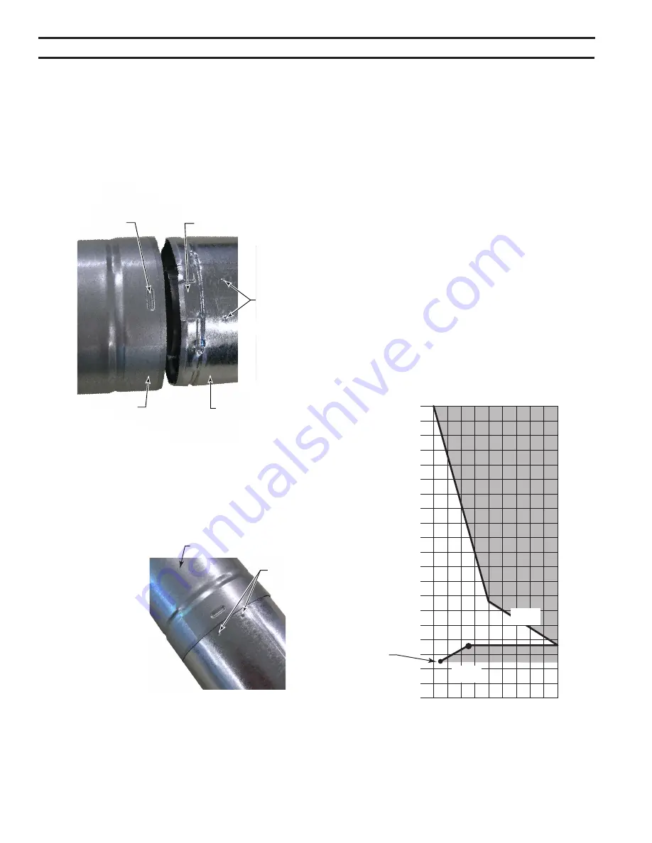
To join T-Lock pipes together, simply align both inner and 
outer pipes with the next section. Align the internal beads 
of  the  female  end  with  the T-channels  of  the  male  end. 

Figure 10

Insert  male  end  until    beads  on  the  female  end  contact 
bottom of T-channel on male end. Twist pipe until beads 
stop at ends of T-channel.

IMportant: pipe can be twisted in either direction. 
however, aLL pIpe SectIonS MuSt Be rotateD In 
the SaMe DIrectIon.

Securing the joints with 
sheet  metal  screws  is 
not required.
To make it easier to as-
semble  the  joints,  we 
suggest  putting  lubri-
cant (Vaseline or simi-
lar) on the male end of 
the T-Lock pipe prior to 
assembly.
To  disassemble  T-
Lock  pipe,  rotate  pipe 
sections  until  internal 
beads  on  female  end 
are  centered  between  the  arrow  indentations  on  male 
end. 

Figure 11.

 Pipe sections will then easily separate by 

pulling straight apart.

FP2741
T-lock undo

Arrow  
Indentations 
on Male End

Female End

FP2741

Figure 11 - 
T-Lock Disassemble

X = 57" (1.5 m) minimum 
(Floor to center of horizontal 
pipe)

FP2740
T lock channels

Internal 
Beads

T-Channel

Female End

Male End

FP2740

Figure 10 - 
T-Lock Pipe Joints

Arrow 
Indentations

Summary of Contents for 400DVBLNV7CE

Page 1: ...installation adjustment alteration services or maintenance can cause injury or property damage Refer to this manual For assistance or additional information consult a qualified installer service agenc...

Page 2: ...ectrical Installation 23 Electrical Wiring 23 Glass Removal 24 Remote Wall Switch Installation 25 Operating Instructions Milli Volt 26 Lighting Pilot for the First Time 26 Lighting Pilot 37 Lighting B...

Page 3: ...ANT SAFETY INFORMATION This fireplace is a vented product This fireplace must be properly installed by a qualified service person The glass door must be properly seated and sealed If this unit is not...

Page 4: ...een submerged in water 18 Do not operate fireplace if any log is broken 19 Do not use a blower insert heat exchanger insert or any other accessory not approved for use with this fireplace 20 Do not op...

Page 5: ...ved for closet or recessed installations product SPECIFICATIONS FP2073 BLDV controls Off Pilot On Knob Figure 1 DVBL7 Series Fireplace Millivolt Control shown Hi Lo Knob On Off RS Switch Ignitor FP207...

Page 6: ...ne Access 400DVBL A 37Z zn 941 mm B 29 737 mm C 40B 1032 mm D 30Z v 768 mm E 17 zn 446 mm F 25ZC zn 656 mm G 31M 810 mm H 31ZB zn 811 mm I 3 76 mm J 1 25 mm K 11C 289 mm L 15 16 24 mm M 15Z 384 mm N 7...

Page 7: ...for your specific installation requirements Refer to Figure 2 for firebox dimensions The framing headers may rest on the top of the firebox standoffs Do not bring headers below top of standoffs NOTE W...

Page 8: ...due to heat from appliance Never obstruct the front opening of the fireplace Do not install in the vicinity where gasoline or other flammable liquids may be stored Vent pipe routing Refer to Venting...

Page 9: ...than wood flooring If installed on carpet or vinyl flooring the appliance shall be installed on a metal wood or noncombustible material panel extending full width and depth of the appliance NOTE All...

Page 10: ...ction Only noncombustible materials i e brick tile slate steel or other materials with a UL fire rating of Zero may be used to cover the black painted face of the appliance It is permissible to bring...

Page 11: ...re rigid direct vent components can be used All restrictions clearances and allowanc es that pertain to the rigid piping apply to the flexible venting Flex kits may not be modified Flex kits may be ad...

Page 12: ...assembly above the meter regulator assembly 5 m above the meter regulator assy I Clearance to service regulator vent outlet 3 91 cm 3 91 cm J Clearance to nonmechanical air supply inlet 6 15 cm for a...

Page 13: ...a minimum of 3 914 mm below the termination cap 3 All gravity air intakes within 3 914 mm of a termination cap must be a minimum of 1 305 mm below the termination cap General Information Assembling Ve...

Page 14: ...de wall to the center of the pipe on the fireplace Vertical Dimension From the Floor of Unit to the Center of the Horizontal Vent Pipe eg A eg B T Lock Pipes When using unitized T Lock pipe it is not...

Page 15: ...on If the vertical rise is 71 2 ft or more only a 1 clearance is needed on top of any horizontal run Vertical sections of this vent system require a minimum of 1 clearance to combustibles on all sides...

Page 16: ...maintained the horizontal vent length is re duced by 36 914 mm Figures 15 16 This does not apply if the 90 elbows are used to increase or redirect a vertical rise Figure 14 12 Min 3 x 90 Elbows FP117...

Page 17: ...he 9B x 9B vent opening Step 3 Place fireplace into position Measure the vertical height X required from the base of the flue collars to the center of the wall opening Figure 19 Step 4 Install the uni...

Page 18: ...02 mm flex vent pipe to the appliance col lar as described on Page 13 Secure the end with the first spring 18C v 476 mm from the flex pipe end to the unit Step 6 Slide the 7 178 mm flex vent pipe over...

Page 19: ...t will be necessary to ex tend vent pipes out as far as the protruding wall face Figure 24 VERTICAL THROUGH THE ROOF APPLICATION his gas fireplace has been approved for Vertical installations up to 40...

Page 20: ...is below the shingles Figure 31 8 Install appropriate pipe sections until the venting is above the flashing Figure 31 9 Install storm collar and seal around the pipe 10 Add additional vent lengths fo...

Page 21: ...ation Vent Storm Collar Flashing Lowest Dis charge Opening Concentric Vent Pipe 1 25 mm Minimum Clearance to Combustibles FP1971 Horizontal Overhang Figure 30 Minimum Chimney Clearance Roof Pitch H fe...

Page 22: ...necessary gas connections to this appliance CAUTION A manual shutoff valve must be installed upstream of the appliance Union tee and plugged pressure tapping point should be installed upstream of the...

Page 23: ...gauge over test point Turn unit to high Figure 33 After taking pressure reading be sure and turn captured screw clockwise firmly to reseal Do not over torque Check test points for gas leaks Electrical...

Page 24: ...amps on bottom of fireplace Figure 34 3 Tilt glass frame out and lift glass frame up until it clears three tabs on top of fireplace 4 Set glass frame aside Each clamp has a quick spring force When rei...

Page 25: ...length provided NOTE Extended lengths of wire may cause the fireplace not to function properly Longer length of wire is permitted if the wire is made out of larger gauge diameter wire Always check wi...

Page 26: ...lified service technician Force or attempted repair may result in a fire or explosion D Do not use this appliance if any part of it has been under water Immediately call a qualified service technician...

Page 27: ...riod of time when the magnet is closed it is possible to start the lighting operation The gas control knob is designed to be operated by hand DO NOT use any tools during this operation Damaged knobs m...

Page 28: ...This switch allows you to turn on and to turn off the main burner without using the gas valve knob Make sure the button is in the ON position to light the main burner Figure 37 Lighting the burner Dep...

Page 29: ...th the pin on the burner Also match the cut out on the bottom of the log with the bars on the grate Note When this log is in place pull towards the front 3 Place the right front log 4 over the burner...

Page 30: ...top right log 2 by resting it over the upper right log and the rear log This log will curve to the middle as it rests over the rear log final installation LG613 DVBL upper rear log LG612 DVBL left fr...

Page 31: ...urner Flame The flames from the burner should be visually checked as soon as the heater is installed and periodically during normal operation In normal operation at full rate and after operating for a...

Page 32: ...s may be used Handle glass door with care to avoid striking or scratching it on hard objects To clean glass door follow Glass Removal procedure outlined in the Final Installation section Film deposit...

Page 33: ...hat the thermocouple connec tion at the gas valve is fully inserted and tight Disconnect the thermocouple from the valve place one millivolt lead wire on the tip of the thermocouple and the other mete...

Page 34: ...ximum flame impingement on thermocouple A Check for flue product leak Replace defective pipe section B Check horizontal venting piping is running upward 1 4 per foot Do not run the pipe level or downw...

Page 35: ...Junction Box Assy not shown 1 26D2128K 2 Sheet Metal Base 1 74D0514 3 Glass Frame Assy 1 74D0096K 4 Control Cover 1 74D0038K Accessories Field Installed Options 5 Decorative Mesh Glass Cover 1 BLDV40...

Page 36: ...20301763 36 DVBL7 Series Gas Fireplace REPLACEMENT PARTS Standing Pilot Millivolt control 1 2C 2I 2T 2 4 5 3 7 8 6 9 10 11 12 13 1763 DVBL7 millivolt parts...

Page 37: ...lacement Thermopile 1 37D1068 37D1068 3 Burner Tube 1 74D0049K 74D0049K 4 Rocker Switch 1 41D0048 41D0048 5 Piezo Igniter 1 14D0503 14D0503 6 Injector 1 20H3147 33D5039 7 Burner Assy 1 74D0098K 74D009...

Page 38: ...LACEMENT PARTS 1 6 5 2 3 4 743000 BLDV log parts Ref Description Qty 400DVBL 1 Rear Log 1 1 74D0059 2 Top Right Log 2 1 74D0060 3 Front Upper Log 3 1 74D0061 4 Right Front Log 4 1 74D0062 5 Left Front...

Page 39: ...Pipe 30 pack 47TL36 30 48 Vent Pipe 47TL48 48 Vent Pipe 30 pack 47TL48 30 T Lock Elbows 45 Elbow for Vertical Horizontal Offset 47TLE45 45 Elbow for Vertical Offsets 8 pack 47TLE45 8 90 Elbow for Ver...

Page 40: ...ent Length 47TL1218 35 64 Adjustable Vent Length 47TL3564 8 Vent Pipe 4 pack 47TL8 4 12 Vent Pipe 4 pack 47TL12 4 24 Vent Pipe 4 pack 47TL24 4 36 Vent Pipe 47TL36 36 Vent Pipe 30 pack 47TL36 30 48 Ven...

Page 41: ...20301763 41 DVBL7 Series Gas Fireplace...

Page 42: ...20301763 42 DVBL7 Series Gas Fireplace...

Page 43: ...fetime Warranty will also be void if the appliance is not operated and maintained according to the operating instructions supplied with the appliance and does not extend to 1 firebox burner assembly d...

Page 44: ...MHSC 149 Cleveland Drive Paris Kentucky 40361 www mhsc com...

Reviews: