background image

© MGG Products New Zealand 2021 


Index 


           Page Number


Contents    


Additional items you may need  


Key-terms   


Suitable for  


How the system works  


Warranty   


Operating Guide 
 

STEP 1: Positioning the transmitter 


STEP 2: Laying out the system 


STEP 3: Layout the proposed boundary-wire   


STEP 4: Connecting the boundary-wire to the transmitter   


STEP 5: Preparing the collar-receiver    


STEP 6: Setting the boundary width & testing the Collar-receiver  

10 

STEP 7: Installing the boundary wire  


11 

STEP 8: Placing the boundary training flags    


12 

STEP 9: Fitting the collar-receiver   


12 

Step 10: Training Guide 


13 

 
Trouble-shooting  


17 


Short loop test    


18 

 
Locating a break in the wire  


18 

 
Terms of use and limitation of liability  


19 

 
Caution    


19 


MGG offer a return-to-base warranty for 12 months against faulty manufacture 

Please retain your original invoice for warranty purposes 


Summary of Contents for Maxi

Page 1: ...INSTRUCTION MANUAL For warranty purposes please read the entire instruction booklet BEFORE set up of the system Made in China for MGG Products Kerikeri 0230 New Zealand www mggproducts co nz info mggproducts co nz ph 0800 449 669 ...

Page 2: ...ransmitter 8 STEP 5 Preparing the collar receiver 9 STEP 6 Setting the boundary width testing the Collar receiver 10 STEP 7 Installing the boundary wire 11 STEP 8 Placing the boundary training flags 12 STEP 9 Fitting the collar receiver 12 Step 10 Training Guide 13 Trouble shooting 17 Short loop test 18 Locating a break in the wire 18 Terms of use and limitation of liability 19 Caution 19 MGG offe...

Page 3: ...s signals to return the dog to the dog containment area Boundary width the distance between the start of the static correction zone and the boundary Collar receiver the device that receives the radio signal from the boundary wire Prongs contact points the metal prongs which screw onto the collar receiver These are the contact points through which the collar receiver delivers the safe static correc...

Page 4: ...ags to act as a visual aid during your dog s training period When dog containment is required your dog will wear the collar receiver with the prongs making direct contact with the skin of the neck Once trained in the dog containment area and aware of the static correction zone your dog can then roam freely within the designated dog containment area If your dog reaches the static correction zone th...

Page 5: ...g the layout for the Dog Containment Area It is recommended that you read this entire manual BEFORE planning the design of your dog s containment area This will save time and avoid unnecessary changes Design a layout that is suitable for your yard Sample layouts are provided in this section The boundary wire MUST START at the transmitter make a continuous loop back to it 2A Always use gradual turn...

Page 6: ...ransmitter run the wire to A A to B B to C C to D D to E E to A twist the wires from A back to the transmitter See Install the boundary wire section for further details regarding attaching the boundary wire to a fence Sample 3 Double loop If you are NOT establishing the boundary zone on all sides of your property as in samples 1 2 a double loop MUST BE USED Caution When using a double loop the bou...

Page 7: ...res together Strip away approximately 3 4mm of insulation from the ends of the boundary wires to be spliced Make sure the exposed copper boundary wire is not corroded If the wire is corroded cut it back further to expose clean copper wire Insert the stripped ends into the MGG waterproof heatshrink joiners supplied with the system Crimp the centre of the joiner together firmly with a pair of pliers...

Page 8: ... insert the other end of the cable into the power input socket of the transmitter Both the power light and the loop indicator light should come on If this does not happen see the Troubleshooting section page 17 Ground wire 4B If you are not using an anti surge device effective grounding is required to minimise the risk of electrical power surges which can damage the transmitter and or power adapte...

Page 9: ...ng of your dog Charging the collar receiver 1 Connect the charging cable to the mains adaptor Plug into the mains switch on then connect to the collar receiver A RED light on the collar receiver indicates it is charging 2 When fully charged the red light changes to BLUE 3 Disconnect the collar receiver from the adaptor the blue light will turn off 4 Switch off the mains power to the adaptor 5 The ...

Page 10: ...ry wire being used Then select the appropriate setting with the boundary control switch located on the side of the transmitter 6A There are THREE settings A use this setting for distances of over 750m of boundary wire B use this setting for up to 400m of boundary wire C use this setting for distances between 400m 750m boundary wire Once the boundary control switch has been set to the correct lengt...

Page 11: ...ht should flash This indicates the static correction has been delivered 6G It is recommended that you repeat this test in several areas of the dog containment area to ensure the system is working where it is intended Once complete remove the test light from the collar receiver prongs You are now ready to complete the installation of the boundary wire If the collar receiver did not beep and the tes...

Page 12: ...A Place a boundary training flag in the ground 8B Walk back into the dog containment area until the beeping stops Repeat this process around the entire perimeter of the dog containment area until it is marked with boundary training flags approximately every 3 metres With the boundary wire fully installed the collar receiver tested and static correction zone marked with training flags it is time to...

Page 13: ... the Maxi Dog Containment System Read this section completely before embarking on training your dog Remember that the MGG Maxi Dog Containment System is not a solid barrier Training is a process as follows Be patient with your dog Training should be fun fair firm and consistent Make training sessions short Train for a maximum 10 to 15 minutes at a time Do not try to do too much too quickly Frequen...

Page 14: ... the collar receiver on page 10 3 Place the collar receiver on your dog positioning it BELOW the additional collar and leash 4 Begin by walking the dog towards the boundary training flags 10A Keeping your mood relaxed and with full control of your dog on the leash toss a treat beyond the boundary flags and within the static correction zone Allow your dog to enter the static correction zone to atte...

Page 15: ... is showing any indicators of stress as listed on page 13 Important For some dogs the BEEP is a sufficient warning signal as to the boundary line whilst others will require the combination with the static correction Always start at the lowest level of intensity of static correction and increase in gradual increments of intensity as outlined in Setting the warning intensity on the collar receiver o...

Page 16: ...nsupervised freedom within the dog containment area When you are satisfied that your dog s training is complete remove every other boundary flag once a week until all the flags are removed Save boundary flags for future use Taking your dog outside of the dog containment area Once training is completed your dog will be familiar with the boundary of the dog containment area and will be reluctant to ...

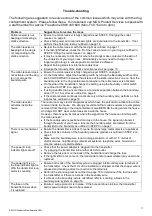
Page 17: ...rm a short loop test as outlined on page 18 The collar receiver activates inside the house There are too many electrical appliances which have the potential to activate the collar receiver inside the house We strongly recommend that collar receivers are completely removed from the dog in the dog containment area BEFORE the dog enters the house And dogs DO NOT wear collar receivers inside the house...

Page 18: ...r receiver next to the test loop wire The collar receiver should beep up to 30cm away from the test loop wire The test light should flash as you hold the collar receiver closer to the test loop wire 9 If the collar receiver does not beep and or the test light does not flash try re charging the collar receiver and repeat the test again 10 When the collar receiver beeps and the test light flashes th...

Page 19: ...ve incidental special or consequential damages or any damages whatsoever arising out of or connected with the use or misuse of this product Buyer assumes all risks and liability from the use of this product 5 Modification of terms and conditions MGG Products reserves the right to change the terms conditions and notices under which this product is offered CAUTION The MGG Maxi Dog Containment System...

Page 20: ...20 MGG Products New Zealand 2021 Made in China for MGG Products Kerikeri 0230 New Zealand www mggproducts co nz info mggproducts co nz ph 0800 449 669 ...

Reviews: