Comet installation and user manual: E-6761200XT/FA
Merlin Gerin by MGE UPS SYSTEMS
10.3
Installation of an emergency off function must be carried out in compliance with
applicable regulations. When an external emergency off function is activated, the
AC input to Comet must be cut to ensure protection of life and property.
However, this action does not cut the supply of power to the load protected by
Comet because the system continues to operate on battery power.
To power down the entire installation via an emergency off function, the action
must also turn off the following via a single device:
■
the battery circuit breaker 4 ;
■
the circuit breaker for the additional battery cabinet(s), if applicable;
■
and a circuit breaker placed downstream of the UPS, otherwise the UPS output
remains live for approximately 3 seconds after the emergency off function has
been activated.
This requires installation of an MX shunt trip.
■
check that the upstream circuit breaker on the low voltage switchboard is in "off"
position;
■
check that the input power switch 1 and the battery circuit breaker 4 are in
"off" position;
■
remove the connection cover panel 13 from the Comet;
■
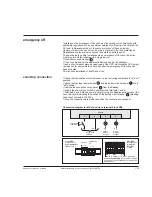
supply the shunt trip coil with AC power across terminals 1 and 4;
■
terminals 2 and 3 may be used to supply (using a voltage identical to that of the
shunt trip) lights indicating the position of the battery circuit breaker 4 (breaking
capacity of contacts is 1300VA);
■
once the connections are made, reposition the connection cover panel.
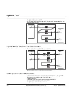
emergency off
shunt trip connection
Connection diagram for MX shunt trip to terminal block XR3
1
4
2
3
Comet
N
Ph
N
N
emergency
off button
220 to 240V
50/60Hz
circuit
breaker
on light
circuit
breaker
off light
battery
emergency
off
L+
1 2 3 4
L–
Comet XR3
terminal block
(exept Comet S11
/ S31 of 5kVA)
1 2 3 4
XR3
battery
XR1
Mains 2 (optional)
XR1/XR3
terminal block
for Comet
S11 / S31
of 5kVA
XR3
emerg. off
secure the shielding of the cable to the stud
provided on the connection cover panel (see
appendices).


