
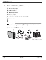
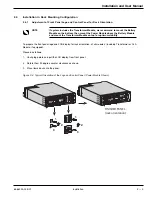
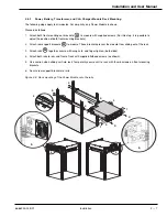

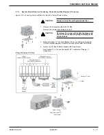


NOTE:
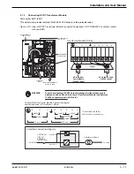
This step is unique to the Power Module. It involves the installation of the I/O Box
Bracket System.
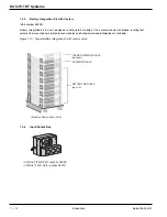
The I/O Box bracket system keeps the I/O Box stationary while hot swapping the Power Module. It will then be
easier to slide the replacement module into the connectors of the I/O Box.
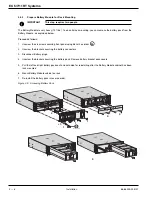
1&2.
Secure small brackets to larger bracket from the underside
.
3.
Secure small attached brackets to the I/O Box with four screws.
4.
Secure large bracket
to rails at the rear of module with four nuts.
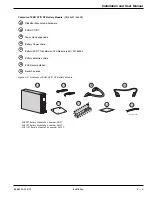
Figure 2-7: Input/Output Box Bracket System.
OFF
1
2
4
4
3
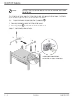
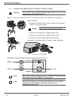
Install input/output cables
per section 2.7 prior to this step.
27
27
EX 5/7/11 RT Systems
Installation
2 — 8
86-86000-00 B01
Summary of Contents for 11+
Page 1: ...w w w m g e o p s c o m EX 5 7 11 RT Systems Installation and User Manual ...
Page 2: ......
Page 4: ... This page left blank intentionally EX 5 7 11 RT Systems iv 86 86000 00 B01 ...
Page 14: ... This page left blank intentionally EX 5 7 11 RT Systems c x 86 86000 00 B01 ...
Page 46: ... This page left blank intentionally EX 5 7 11 RT Systems 2 20 86 86000 00 B01 ...
Page 62: ... This page left blank intentionally EX 5 7 11 RT Systems 4 6 86 86000 00 B01 ...
Page 68: ......
Page 72: ...EX 5 7 11 RT Systems G 4 86 86000 00 B01 This page left blank intentionally ...
Page 74: ......
Page 75: ......