background image

people, pets, clutter and debris. Never assemble or install any antenna near 
power lines or residential entrance cables!  
 

Important Warning: This antenna is an electrical conductor and, if it comes 
into contact with power lines, you can be KILLED. Never assemble or 
install any antenna near power lines!  


Tools: 

7/16" and 5/16" nut drivers, #2 phillips-head screwdriver, diagonal cutters. 

 
Assembly Instructions:  
 

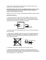
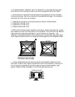
[  ] Locate one of the 8" x 8" aluminum mounting plates and install the mast-
mount bracket using four (4) 3/8" screws and nuts. Insert screws so the nuts 
install on the 

mast-mount

 side of the plate. This is the side that will be oriented 

toward the ground during final assembly and installation. 


Mounting

Bracket

Holes

Mounting Plate


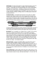
[  ] Locate the second mounting plate and position it so 

all mounting holes

 align 

with the first plate. 
  
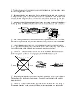
[  ] Install one of the fiberglass support arms as shown, inserting it between the 
two plates and securing it with two (2) 1" screws and nuts. Insert screws so the 
nuts install on the mounting bracket side of the plate. Finger-tighten for now – 
they will be tightened later. 


Mounting Plate

Install Tubes Between 

the Two Mounting  Plates


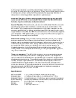
[  ] Install the remaining three spreader arms in the same manner.  
 
[  ] Locate the matching-network support arm. Before installing, observe the 
tube's mounting hole pattern closely. One set of holes will be closer to the end of 
the tube than the set at the opposite end. Install using the pair of holes 

closest to 

the end

 using two (2) 1" screws and nuts. 


Summary of Contents for MFJ-1835

Page 1: ...12 15 17 20 Meter Cobweb Antenna Instruction Manual Caution Read All Instructions Before Assembling and Using This Product MFJ 300 Industrial Park Road Starkville MS 39759 USA Tel 662 323 5869 Fax 66...

Page 2: ...35 4 72 Fiberglass Element Support Tube 811 1835 1 1 43 Fiberglass Feed Tube 811 1835 2 1 50 Ohm to 12 5 Ohm Match Box 10 1835 1 1 Mast Mounting Bracket 735 1835 5 Element End insulators 12 x 5 737 01...

Page 3: ...d during final assembly and installation Mounting Bracket Holes Mounting Plate Locate the second mounting plate and position it so all mounting holes align with the first plate Install one of the fibe...

Page 4: ...rt tube The two remaining tie wraps may be used later to secure your coax to the feed tube Install flat washers on four 4 1 inch screws and insert them at the four 10 meter spreader locations holes ne...

Page 5: ...ng the rig lugs as needed to other mounting holes in the insulators Do not tension the wires so tightly that they distort the spreaders or pull the frame out of square The objective is to equalize ten...

Page 6: ...clear of the insulator and add a short length of wire using a 6 32 screw Bandwidth The 2 1 bandwidth for a half wave loop is normally much narrower than it is for a straight line half wave dipole so...

Page 7: ...tallation using one or more runs of 10 solid aluminum ground wire Also always install a barrel connector or junction box where the cable enters your building and unhook it at the first sign of threate...

Page 8: ...ners who attempt to repair defective units Technical consultation is available by calling 662 323 5869 5 This warranty does not apply to kits sold by or manufactured by MFJ Enterprises Inc once assemb...

Reviews: