background image

MFJ-1623 Instruction Manual 

Window/Balcony  Mount Antenna 


3

Using the MFJ-1623 


CAUTION

Never Change The Antenna or Inductor Selector Switch Position While 
Transmitting!  Never Apply More Than 200 Watts To The MFJ-1623. 

 
Preset the controls on the MFJ-1623 as follows: 

• 

ANTENNA to maximum inductance - Position "A". 

• 

MATCHING to minimum capacitance – Position “10” 

• 

NORM/+C switch to NORM 

• 

COUNTERPOISE to minimum inductance – Position “L” 

• 

Hi-Z/Lo-Z switch (back of unit) to Lo-Z. 

• 

SENSITIVITY control fully clockwise (maximum sensitivity) 

 
Most modern solid state transceivers do not require tuning and loading adjustments.  If the transceiver 
has a built in antenna tuner, be sure it is turned off or disabled.  If your transmitter has an adjustable 
output circuit, it must be properly tuned to a 50 ohm load at the operating frequency before adjusting 
the tuner.  This should be done with a dummy load.   
 

Tuning Procedure 


WARNING:  

Never transmit while changing the INDUCTOR SELECTOR. 

 
1)  First, tune for maximum receiver noise as follows: 

• 

While listening to your desired receive frequency, adjust the ANTENNA control for 
maximum receiver noise. 

• 

Adjust the MATCHING control for maximum receiver noise. 

• 

Adjust the COUNTERPOISE control for maximum receiver noise. 

Note:  If no noise peak is evident, try adding extra capacitance with the NORM/+C 
switch.  Then reverse the HI-Z/LO-Z switch and re-try with both positions of the 
NORM/+C switch. 

2)  Apply just enough power on CW (or AM/FM/RTTY) to obtain a noticeable deflection on the RF 

CURRENT meter. 

3)  Carefully adjust the ANTENNA, MATCHING and COUNTERPOISE controls for maximum RF 

current as follows. 

• 

Adjust the MATCHING capacitor for maximum RF current. 

• 

Adjust the COUNTERPOISE inductor for maximum RF current. 

• 

Try plus or minus a position or two on the ANTENNA inductor, along with tuning the 
MATCHING capacitor to see if higher RF current is achievable. 

Summary of Contents for 1623

Page 1: ...uning controls and only one tuning solution for given impedance match The MFJ 1623 has rear panel connectors for coaxial input and a Hi Z Lo Z switch for reversing the L network An internal input isolating current balun provides isolation of DC and RF grounds for optimum tuning of the RF counterpoise An RF Current Meter indicates the summed antenna and counterpoise antenna currents making tuning p...

Page 2: ...ch the mounting bracket in position by placing the bracket over or around the surface of the support NOTE THE ANTENNA SHOULD BE ORIENTED AWAY FROM WINDOWS AND OTHER OBJECTS THAT ARE WITHIN CLOSE RANGE IF POSSIBLE 4 Tighten the screws on the rear of the base plate against the surface of the support The screws should be tightened in equal increments to keep the force on the spacer plate proportioned...

Page 3: ...he tuner This should be done with a dummy load Tuning Procedure WARNING Never transmit while changing the INDUCTOR SELECTOR 1 First tune for maximum receiver noise as follows While listening to your desired receive frequency adjust the ANTENNA control for maximum receiver noise Adjust the MATCHING control for maximum receiver noise Adjust the COUNTERPOISE control for maximum receiver noise Note If...

Page 4: ...imize RFI antennas should be kept away from other wiring as much as possible Also the antenna should be adequately insulated to prevent arcing or accidental contact if placed near other objects For safety it is always best to use both dc and RF grounds A DC ground may not be practical in some portable locations however It is always important to have a good RF ground provided by the counterpoise wh...

Page 5: ...ch is properly set Installation of a Suitable Counterpoise Artificial Ground The MFJ 1623 includes a counterpoise set of wires that will work well from 80 10 meters It is important to keep the last few feet of the counterpoise wires as far as possible two feet minimum from each other and other near by conductors You can also build your own counterpoise system if you desire A RF counterpoise system...

Page 6: ...mizing RF Current described in the tuning procedure WARNING This unit does NOT provide a dc or ac safety ground through the COUNTERPOISE terminal A separate wire from the station ground bus to an electrical or earth ground must be used TVI and RFI Hints It is possible for RF to flow down power cables into the house wiring This may cause TVI Stereo VCR or other RFI problems As a precaution a ferrit...

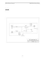
Page 7: ...MFJ 1623 Instruction Manual Window Balcony Mount Antenna 7 Schematic ...

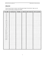
Page 8: ...ake a copy of this page and place it near the tuner Insert your own values for each frequency according to your station Freq MHz Counterpoise Matching Antenna Hi Lo Z switch Extra cap switch 1 8 1 8 2 0 2 0 3 5 3 5 3 5 3 75 3 75 3 75 4 0 4 0 4 0 7 15 7 15 10 1 10 1 14 2 18 1 18 1 21 2 21 2 24 9 28 5 ...

Page 9: ...MFJ 1623 Instruction Manual Window Balcony Mount Antenna 9 ...

Reviews: