background image

13

15

16

13

1

2

3

4

5

6

7

8

9

10

11

12

14

   11

OVERVIEW

Model 2.322

The overview shows the most important 
components and operating devices of the 
electric wheelchair.

Pos. Description

(1)  Back support
(2)  Arm support
(3)  Seat
(4)  Leg support
(5)  Seat lock
(6)  Calf belt
(7)  Footplate
(8)  Headlights
(9)  Driving wheel
(10) Steering wheel
(11) Front indicator
(12) Operating module
(13) Selection lever drive/push mode resp. 

brake lever

(14) Type plate
(15) Direction indicator light / back light
(16) Rear transport attachment

Summary of Contents for 2.322

Page 1: ...en Operating manual Electric wheelchair Model 2 322 OPTIMUS 2 ...

Page 2: ... 10 Reinstallment 10 Life span 10 Base position 10 Overview 11 Model 2 322 11 Handling the electric wheelchair 12 Securing the electric wheelchair 12 Functional checks 12 Driving 12 Brakes 12 Service brake 12 Braking the wheelchair 12 Emergency braking 12 Parking brake 12 Drum Brake 13 Locking the brakes 13 Releasing the brakes 13 Drive push mode 14 Selecting the push mode 14 Selecting the motor m...

Page 3: ...emoving the calf belt 20 Attaching the calf belt 20 Length adjustment of the calf belt 20 Lower leg support 21 Footplates 21 Footboard 21 Leg support upper part 22 Turning the leg supports to the side 22 Swivelling in the leg supports 23 Removing the leg supports 23 Attaching the leg supports 23 Mechanically height adjustable leg supports 24 Lifting lowering the leg support 24 Electrically height ...

Page 4: ... of the back support angle 30 Lordosis adjustment 30 Ergo Seat 31 Folding down the back support 31 Unfolding the back support 31 Adjusting the back support angle 31 Electrically adjustable back support 32 Folding down the electrically adjustable back support 32 Unfolding the back support 32 Head support 33 Seating system ERGO Seat 33 Retaining strap 34 Rear view mirror 35 Removing the rear view mi...

Page 5: ...ights 43 Fault correction 44 Basic safety information 45 Accompanying person 45 Transfer out of the electric wheelchair 45 Reaching for objects 46 Driving on falling rising or transverse gradients 46 Crossing obstacles 46 Electrical system 47 Transport in public methods of transportation 47 Driving on public highways 48 Cleaning 48 Finish 49 Disinfection 49 Repairs 50 Repairs 50 Customer Service 5...

Page 6: ...22 54 Dimensions with Ergoseat Code 948 950 without head support 56 Dimensions with seat Ergostar Code 961 without head support 57 Meaning of the symbols on the washing instruction 58 Meaning of the labels on the electric wheelchair 59 Meaning of the symbols on the type plate 60 Inspection certificate 61 Warranty Guarantee 62 Warrantee Guarantee section 63 Inspection certificate for transfer 63 ...

Page 7: ... not be applicable for your individual electric wheelchair A list of the available options and accessories can be viewed in the order form of your electric wheelchair Users with visual impairments can find the PDF files together with further information on our website www meyra com Contact your specialist dealer when re quired Alternatively users with visual impairments can have the documentation ...

Page 8: ...habilitation consultant u o This also includes that people that show a counter indications to the named problems in some cases need to give proof of the cognitive mental and moral ability to operate one of the models shown in the list of models The electric wheelchair may not be used in cases of Cognitive limitations and mental re tarding that rule out the independent use of the electric wheelchai...

Page 9: ... and limita tion described in chapter Technical data on page 51 ADJUSTMENT Always have adaptation adjustment or re pair work carried out by a specialist dealer The electric wheelchair offers manifold ad justment possibilities to individual vital sta tistics Before first use an adaptation of the electric wheelchair and a practical instruc tion in the functionalities of your electric wheelchair shou...

Page 10: ...des information to the re installment and reinstallment frequency of your electric wheelchair LIFE SPAN We expect an average life span of about 5 years for this product as far as the product is applied for its designated purpose and all maintenance and service guidelines The life span of your product depends upon the fre quency of use the application environment and care The implementation of spar...

Page 11: ...e electric wheelchair Pos Description 1 Back support 2 Arm support 3 Seat 4 Leg support 5 Seat lock 6 Calf belt 7 Footplate 8 Headlights 9 Driving wheel 10 Steering wheel 11 Front indicator 12 Operating module 13 Selection lever drive push mode resp brake lever 14 Type plate 15 Direction indicator light back light 16 Rear transport attachment ...
Page 12: ...nd steering lever while driving as well as the preadjusted maximum final speed of your electric wheelchair BRAKES Brake the electric wheelchair down care fully and in time This is especially the case when driving in front of people and while driving downhill Service brake The motor works electrically as an oper ating brake and decelerates the electric wheelchair softly and jerk free to a standstil...

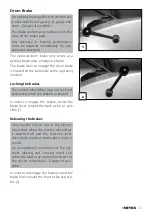
Page 13: ... module Locking the brakes The electric wheelchair may not let itself be pushed when the brake is activated In order to engage the brakes swivel the brake lever toward the back as far as pos sible 1 Releasing the brakes Only transfer into or out of the electric wheelchair when the electric wheelchair is switched off and the selection lever drive push mode on both sides is in drive mode An unintent...

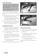
Page 14: ...the back support or the back support itself Selecting the push mode 1 Switch off the operating module be cause the pushing will otherwise be made difficult by the electric system Therefore observe operation manual Operating module 2 First pull up the locking sleeve 2 on the selection lever drive push mode then guide the selection lever toward the back 3 Therefore observe chapter Releasing the brak...

Page 15: ... the following direc tions are to be carried out in the indicated order Charge the drive batteries via the oper ating module before the first journey 1 Establish drive mode 1 Therefore observe chapter Technical data on page 51 2 Loosen the drum brake 2 Therefore observe chapter Drum Brake on page 13 ...

Page 16: ...nd safely steer the electric wheelchair The distance of the operating mod ule to the padded arm supports can be adjusted after loosening the clamping screw 3 4 After the adjustment retighten the clamping screw For this observe chapter Positioning the operating module on page 18 5 Switch the operating module on Press the On Off key 4 on the con trol panel of the operating module Therefore observe o...

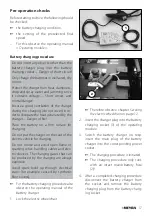
Page 17: ... the seat of the electric vehicle for charging Do not smoke and avoid open flame or sparking when handling cables and elec tric devices The charging gases that can be produced by the charging are always explosive Avoid spark build up through electrical static for example caused by synthetic floor covers For the battery charging procedure also observe the operating manual of the battery charger 1 L...

Page 18: ...ment 1 Afterwards slide the operating module into the desired position In doing so carefully guide the cable and retighten the clamping screw 1 securely Removing the operating module In order to remove the operating module loosen the clamping screw 1 and discon nect the plugged connection 2 4 Do not pull on the cable while do ing so Afterwards pull out the operating module toward the front out of ...

Page 19: ...ng module more easily For regular drive mode the operating mod ule can be swivelled back toward the front until it engages back into the magnetic lock 1 The power of the magnets 3 can be reduced for example with tape on top of the magnets for easier swivelling of the operating module Should the operating module be po sitioned too close to the arm support move it forward before swivelling Height ad...

Page 20: ...ack of the footplates The calf belt must be removed in order to swivel away the leg supports 2 The calf belt is omitted for height ad justable leg supports and is replaced by a calf pad Removing the calf belt For removal the calf belt is to be pulled from the attachment pins 3 Attaching the calf belt For attachment both loops of the calf belt are slid over the attachment pins 4 Length adjustment o...

Page 21: ...is to be folded down again 2 3 Footplates The footplates can be folded outward and up 1 resp inward and down 2 Footboard Fold the footboard up before swivelling away and removing the upper leg support Folding up the footboard In order to fold up the footboard lift the loose end of the footboard 4 as far as pos sible Folding the footboard down In order to fold down the footboard lower the loose end...

Page 22: ... and dust or dirt e g for longer storage Possible function error of the electri cal adjustment To reduce the length of the electric wheel chair the leg supports can be swivelled in ward outward 1 2 Remove the calf belt before swivelling away the leg supports Therefore observe chapter Remov ing the calf belt on page 20 Fold up the footplates resp footboard in or der to swivel away the leg supports ...

Page 23: ...rtant for transport the leg sup ports can be removed 2 Remove the calf belt before swivelling away the leg supports Therefore observe chapter Calf belt on page 20 For removal first swivel the leg support side ways and then remove them toward the top 1 Therefore observe chapter Turn ing the leg supports to the side on page 22 Watch for possible danger of jam ming Attaching the leg supports For inse...

Page 24: ...t Danger of injury If necessary have an accompanying person help during the adjustment procedure Lifting lowering the leg support 1 Before lifting lowering relieve the leg support by an accompanying person by slightly lifting it up 2 Afterwards loosen the clamping lever 1 and have the leg support lifted low ered slowly to the desired level by an accompanying person 3 After the adjustment retighten...

Page 25: ...ight adjustable leg support Danger of jamming The electrically height adjustable leg sup port 1 2 automatically receives electric contact when hooked on Height adjustment For height adjustment raise or lower the leg support to the desired height via the oper ating module 1 2 Therefore observe operation manu al Operating module ...

Page 26: ...locking lever 1 back press it in or fold it up or down Afterwards swivel the leg support sideways and remove it toward the top 2 Therefore observe chapter Turning the leg supports to the side on page 22 Hanging the electrically height adjusta ble leg support into place After attachment swivel the leg sup ports inward Therefore observe chapter Swivelling in the leg supports on page 23 Press the leg...

Page 27: ... supports 1 2 can be adjusted in height to the demands of the user Danger of jamming when adjusting the height of the arm supports if the cush ions are in a deep setting Removing the arm support To remove the arm support loosen the clamping screw 3 first and then pull out the arm support toward the top 4 The operating module must be re moved first if the arm support on the control side is to be re...

Page 28: ...g screw 6 For inserting the operating module observe chapter Inserting the operating module on page 18 Arm supports code 24 Ergostar seat Swivel up the arm supports The arm supports can be swivelled up for an easier transfer to from the seat 7 Adjusting the angle of the arm support By turning the adjustment wheel 8 the an gle of the arm support can be adjusted ...

Page 29: ...ination only when the electric wheelchair is standing on a hori zontal level surface A danger of tipping over exists on gradients The seat angle adjustment is not linked with an automatic speed reduction func tion An increased danger of tipping over exists with a reclined back support Before driving make sure that you have not adjusted a negative seat inclination resp that the seat inclination ens...

Page 30: ...ed down ward Let the locking lever latch at the next latch ing position after having adjusted the back support angle 1 Check the lock of the back support Watch for possible jamming areas Lordosis adjustment To adjust the lordosis support turn the handwheel 3 counter clockwise into the desired position Watch for possible jamming areas ...

Page 31: ...e cable 1 Watch for possible jamming areas Release the wire cable in order to lock the back support in the desired position 3 Slide the back support until the pressure bolts audibly click into place If required replace the seat pad The greasing of the thrust bolts is rec ommended for an easier latching of the backrest Check the secure locking in of the back support Adjusting the back support angle...

Page 32: ...d the electrically adjustable back sup port 2 down first press the release button 3 then remove the pin 4 Keep the back support in position with one hand at the push bar Afterwards fold the back support down 2 Reinsert the pin 4 in order to prevent loss Unfolding the back support After raising the back support 1 remove the pin 4 lift the gas pressure spring and hang it into place The reinsert the ...

Page 33: ...acket maximally up to the marking The head support solely serves to support the head during regular use but it cannot replace a head support firmly mounted into an automobile during passenger transport When adjusting the head support watch for possible danger of jamming in the area of the adjustment devices The head support is swivel proof height and depth adjustable and removable Seating system E...

Page 34: ... the driver during transport in mo tor vehicles The retaining strap 1 is screwed onto the respective back frame tube 2 The retaining strap serves to stabilise the sitting position and prevents falling forward out of the electric wheelchair To fasten the retaining strap pull both ends forward and audibly let the buckle click into place 1 To open the retaining strap press down the release button 3 a...

Page 35: ...rt the rear view mirror from the front into the arm support tube and tighten the clamping screw 1 Adjusting the rear view mirror 1 Preadjust the rear view mirror by turn ing the clasp 2 Turn the rear view mirror on the attach ment rod and ball joint until you reach the desired angle WALKING AID HOLDER The walking aids may depending on the adjusted length of the walking aids pro trude over the cont...

Page 36: ...rve the operating manual Oper ating module Always switch on the lighting system in poor visibility conditions and especially during darkness in order to see better and be better seen by others Ensure that headlights turn signals and taillights as well as reflectors are not covered by clothes or other objects at tached to the electric wheelchair ...

Page 37: ...o lift the electric wheelchair The electric wheelchair must be switched off before lifting The parts detached for loading must be carefully stowed and carefully attached again before the next journey No special carrying points are allocated for carrying detachable components The following procedures may be necessary due to lack of space for the transport in ve hicles Remove the leg supports Remove...

Page 38: ... anchor positions are marked with a hook symbol For this also observe chapter Mean ing of the labels on the electric wheel chair on page 59 The procedure for securing the electric wheelchair can be read in the docu ment Safety and general handling instructions electric vehicles chapter Transport in motor vehicles or with con veyors This document and further information are available in the Infor m...

Page 39: ... caused by wear or chemical processes of the tyres MAINTENANCE An incorrect or neglected cleaning and maintenance of the electric wheelchair re sults in a limitation of the product liability Maintenance The following maintenance Instruction gives you a guide for carrying out the main tenance work This maintenance schedule does not give information about the actual ex tent of work required on the e...

Page 40: ...n be pushed have the brakes repaired immediately by the specialist workshop Danger of accidents Especially before driv ing in the dark Lighting Check the lighting equip ment and reflectors for flawless functioning Carry out test yourself or with a helper Every 2 weeks depending on dis tance covered Check air pressure of the tyres Tyre filling pressure View Technical data on page 51 Carry out test ...

Page 41: ...mand Every 2 months depending on dis tance covered Check tyre profile Minimum tread 1 mm Carry out a visual check your self or with a helper If the tyre profile is worn down or if the tyre is dam aged consult a specialist workshop for repairs Every 6 months depending on fre quency of use Check Cleanness General condition View chapter Cleaning on page 48 Manufacturer recom mendation Every 12 months...

Page 42: ...a level surface and secure it from rolling away Therefore observe chapter Securing the electric wheelchair on page 12 New fuses can be obtained for example at petrol stations If the safety fuse blows again take the battery to a specialist dealer for repair Fuse Mains battery fuse 1 The flat fuse for the main battery current is located in the fuse holder under the seat on top of the batteries 2 ...

Page 43: ...ng of the light 1 must be adjust ed so that the light cone is visible on the driving surface The lower edge of the light cone should be set at distance of 3 meters to the front of the electric wheelchair The lighting case might need to be re adjusted after adjustment of the seat inclination If needed go to a specialist workshop for adjustment Press down the dispersion disc 1 at the upper or lower ...

Page 44: ...sh mode Swivel the selection le ver drive push mode to drive mode Plugged connection on the drive misses contact Check plugged connec tion Malfunction in the elec tronics Have it repaired by the specialist workshop Push mode Selection lever in driving mode position Not listed faults View Error diagnostics in the operating manual for the operating module Lighting not active Filament bulb defective ...

Page 45: ...u should not smoke while using the electric wheelchair Exposure to direct sunlight can cause seat covers upholstery arm support pads leg supports and handles to heat up to over 41 C Contact with exposed skin can result in injury Prevent such heating by parking the electric wheelchair in a shad ed area Special receptacle point for the attach ment of carry along items is the optional baggage rack On...

Page 46: ... tion and begin to slide out of control If re quired immediately bring the joystick back into the neutral position Never drive faster than walking speed The braking force transferred to the driving surface is much less on a downward slope than on a level driving surface and is fur ther reduced by poor road conditions e g rain snow grit dirt A dangerous slipping of the wheels due to excessive braki...

Page 47: ...the electric wheelchair react in an unaccustomed manner or fulfil uncontrol lable manoeuvres the joystick director is to be brought back into the neutral position initial position immediately and or the elec tric wheelchair to be switched off at once Transport in public methods of transportation Your electric wheelchair is not designed for user transport in public transportation vehi cles Limitati...

Page 48: ...endent driving of the electric wheelchair is required CLEANING The plastic panelling is attacked through non ionic tensides as well as solvents and especially alcohol Do not clean the electric wheelchair with a high pressure cleaner Danger of short circuit The cushions and covers are normally fit with care instructions instruction for care For this observe chapter Meaning of the symbols on the was...

Page 49: ...e touched up with our paint pen availa ble at the specialist dealer Slight lubrication of moving parts will en sure for their long functioning Disinfection If the product is used by more than one per son for example in a care centre the use of a commercial disinfectant is mandatory Before disinfection the upholstery and handles are to be cleaned A spray or wiping disinfection is per mitted with te...

Page 50: ...te the corresponding serial number SN of the electric wheel chair You will find this on the type plate Whenever repair work on the electric wheelchair is carried out by the specialist dealer the supplementary information e g assembly operating instructions must be attached to the operating manual of the electric wheelchair the date of the modifi cation must be recorded and stated when ordering spa...

Page 51: ...yre pressure drive wheel Standard 3 0 4 0 bar 44 58 psi Ultra light running tyres 6 bar 87 psi High pressure 8 bar 116 psi Maximum range The nominal values indicated by are reason able in compliance with ISO 7176 4 The maximum range depends to a large ex tent on the following factors battery condition weight of the driver driving speed driving style road surface condition driving conditions ambien...

Page 52: ... 12184 2014 ISO 7176 8 2014 ISO 7176 19 2008 Assessment of the Crashtest in which the electric wheelchair is at tached to the retaining system of the vehicle has been carried out according to the testing methods of annex D The model Optimus 2 has been assigned the Use Class C as per the EN 12184 stand ard The applied parts and components we use are in compliance to EN 1021 2 for resistance against...

Page 53: ...0 Back support angle 10 50 Back support height 580 mm 640 mm Foot support to seat lower shank length 380 mm 550 mm Static stability downhill 15 5 Static stability uphill 15 5 Static stability lateral 15 5 Dynamic stability uphill 10 Angle leg support seat surface 110 180 Arm support height from seat surface 190 mm 280 mm Back support to front edge of arm support 280 mm 420 mm Possible obstacle hei...

Page 54: ...10 km h values in for 15 km version kg 140 130 kg Ground clearance drive 110 mm Ground clearance battery tub 140 mm Empty weight with drive batteries 120 kg 152 kg Empty weight without drive batteries 72 kg Overall height 1100 mm 1300 mm Transport dimensions Length without leg supports 1030 mm 1340 mm Width without arm supports 680 mm Height Back support folded forward onto the seat 780 mm 950 mm ...

Page 55: ...50 6 14 ø 360 mm pneumatic 2 5 bar 35 psi Drive batteries 2 x 12 V 70 Ah 5 h 79 Ah 20 h sealed maintenance free 2 x 12 V 80 Ah 5 h 97 Ah 20 h sealed maintenance free 2 x 12 V 105 Ah 5 h 120 Ah 20 h sealed maintenance free Max battery dimensions LxWxH 345 x 174 x 262 mm Charging current 6 A 12 A ...

Page 56: ...mm Seat width with code 43 380 mm 500 mm Seat width with code 48 480 mm 560 mm Seat height mm 580 mm Seat inclination 5 20 Back support height 540 mm Arm support height from upper edge of seat 170 mm 270 mm Transport dimensions without leg supports without head support Length mm 1030 mm Width 680 mm Height Back support folded forward onto the seat mm 780 mm ...

Page 57: ...eat height mm 590 mm Seat inclination 7 22 Back support height 640 mm Arm support height from upper edge of seat code 24 210 mm 250 mm Arm support height from upper edge of seat code 106 150 mm 250 mm Transport dimensions without leg supports without head support Length back support to front mm 1030 mm Length back support to rear mm 1340 mm Width 680 mm Height back support to front mm 950 mm Heigh...

Page 58: ...he symbols correspond to European standard Wash as delicates with the indicated maximum temperature in C Wash as regular laundry with the indicated maximum temperature in C Hand wash only Do not bleach Not suited for the dryer Do not iron Do not dry clean ...

Page 59: ...he arm supports or leg supports Removable parts are not suitable for carrying Drive mode Push mode Push only on level surfaces Indication for charging socket The electric wheelchair is not approved as a seat within a motor vehicle Indication for danger of jamming Do not reach in here Operation in moving transport vehicles Switch off or switch to driving program 3 ...

Page 60: ...tal weight Permitted axle weights Max permissible rising gradient Max permissible falling gradient Permitted maximum speed The product is approved as a seat within a motor vehicle Max permitted user weight if the product is approved as a seat within a motor vehicle The product is not approved as a seat within a motor vehicle Medical device ...

Page 61: ...nths Date Place date Signature Stamp of specialist dealer Next safety inspection in 12 months Date Place date Signature Serial no SN Delivery note no Model 61 Recommended safety inspection 1st year at least every 12 months INSPECTION CERTIFICATE Electric wheelchair data Recommended safety inspection 3rd year at least every 12 months Recommended safety inspection 2nd year at least every 12 months R...

Page 62: ...sed dealers as well as maintenance and inspections in regular intervals Guaranty is not granted for surface dam ages tyres of the wheels damages due to loosened screws or nuts as well as worn out attachment holes due to frequent assembly work Furthermore damage to the drive and elec tronics caused by improper cleaning using steam cleaning equipment or the deliberate or accidental flooding of the c...

Page 63: ...cialist dealer Serial no SN Delivery note no Model Stamp of specialist dealer Next safety inspection in 12 months Date Place date Signature 63 Warrantee Guarantee section Please fill out Copy if necessary and send the copy to the specialist dealer Inspection certificate for transfer Electric wheelchair data ...

Page 64: ...Ring 2 32689 Kalletal Kalldorf GERMANY Tel 49 5733 922 311 Fax 49 5733 922 9311 info meyra de www meyra de Your specialist dealer 205 340 001 Status 2021 05 All technical modifications reserved Original operating manual ...

Reviews: