


3 R 74 en
11
4.8
Assembly
❑
Put the bearings (16, 17) in their places.
❑
Mount the seat as explained in Section 4.5.2.
❑
Mount the segment in the body in the closed
position. In the low Cv version, insert the filling
ring (22) between the drive shaft (11) and seg-
ment (3). Press the segment to fit the shaft (12).
❑
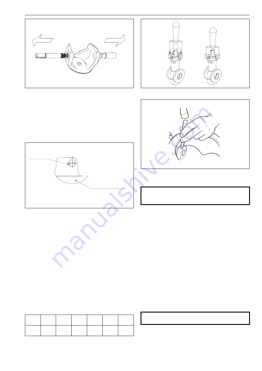
Install the drive shaft (11). Note the location of
the pin hole and the keyway. See Figs. 27 and 28.
❑
Please note the depth of the hole (L) for the coni-
cal pin, Fig. 26. Use a former to check the proper
shaft position of low Cv valves, see Fig. 29 . Put
the pins (14, 15) in their places and lock them,
Fig. 30. Both pins are locked with TIG welding in
the high-consistency acid-resistant version and
in the standard and high-consistency titanium
versions. Moreover, the drive shaft is welded to
the segment in the high-consistency versions.
Contact the manufacturer for more information.
❑
Install the blind flange (10) with gaskets (19),
tighten the bolts (26), see Table 4.
❑
Install the gland packing according to
Section 4.2.
5
TESTING THE VALVE
We recommend that the valve body be pressure tested
after the valve has been assembled.
The pressure test should be carried out in accordance
with an applicable standard using the pressure rating
required by the pressure class or flange bore of the valve.
The valve must be in the open position during the test.
If you also want to test the tightness of the closure
member, contact the manufacturer.
6
INSTALLING AND DETACHING THE
ACTUATORS
6.1
General
Different Metso actuators can be mounted using suita-
ble brackets and couplings. The valve can be operated,
for example, by actuators of the E, B1 or Quadra-Powr
series.
6.2
Installing EC and EJ actuators
The actuator is attached to a valve via an ISO 5211 stand-
ard mounting interface. The actuator is adapted to the
valve shaft with a separate bushing. The bushing (II + II) is
Fig. 27
Removing the shafts
Fig. 28
Segment and shaft positions
Table 4
Screw torques (for lubricated screws)
Screw
M6
UNC 1/4
M8
UNC 5/16
M10
UNC 3/8
M12
UNC 1/2
M16
M29
Torque,
Nm
8
18
35
65
170
330
Spherical surface
marker line
Fig. 29
Using a former to check shaft position
Fig. 30
Locking a pin
CAUTION:
Pressure testing should be carried out using equip-
ment conforming to the correct pressure class!
CAUTION:
Beware of the segment movement!


