Model PDP Series 200 maxDPU4F Hardware Guide
Metso Automation
•
278705
•
4-4
Interpreting Virtual I/O LED Status during Normal DPU Operation
The previous DPU (DPU4E) contained four I/O LEDs. The DPU4F contains
one I/O LED that is the combination of the four. The maxVUE DPU4F
Detail and DPU4FPair Detail displays show the four individual “virtual”
LEDs. These LEDs display the status of each of the four I/O queues. In
general, the I/O cards of a given type are assigned to the labeled LEDs;
however, due to I/O bus transaction processing requirements, some of the I/O
modules of different types or different applications are assigned to different
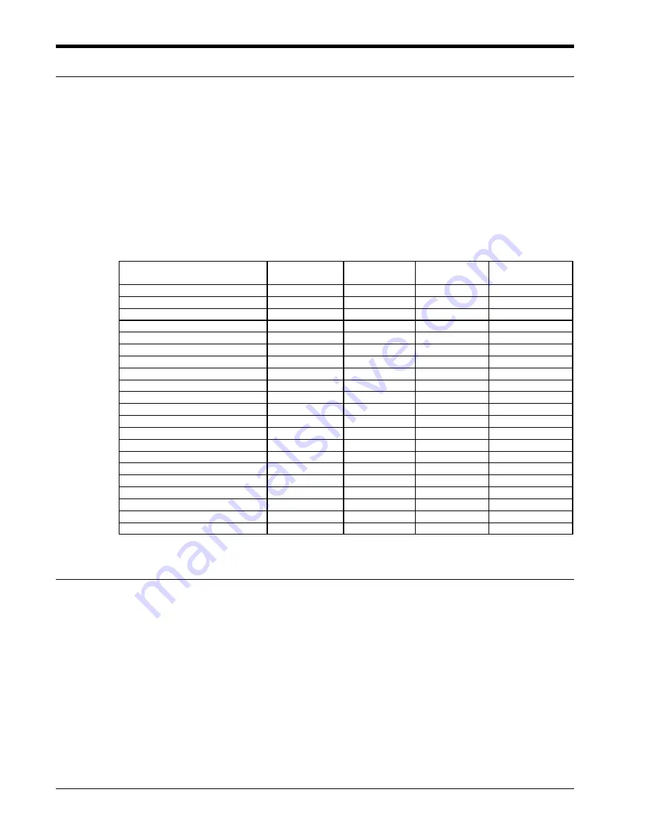
queues. The following table shows the queue assignments for each type or
application of an I/O module.
I/O Card
DI
LED
AO/DO
LED
AI
LED
Unlabeled LED
(Item Queue)
SOE DI
X
Slow DI
X
AI 564
X
TC 564
X
RTD 564
X
AO 564
X
Counter Timer 564
X
Quad PAT 564 or maxPAC
X
X
Output Driver 564
X
DO 564 or maxPAC
X
AI maxPAC
X
X
TC maxPAC
X
X
RTD maxPAC
X
X
AO maxPAC
X
X
Counter Timer maxPAC
X
X
Over Speed Module maxPAC
X
X
Turbine Valve Module maxPAC
X
X
LED Indications During Soft Reset
The CP and State LEDs turn red during the save of the database to the
CompactFlash. The DPU will then reset causing the I/O and CP LEDs to
turn yellow and all others off. See the startup sequence for details about the
restart.
Summary of Contents for PDP 400 maxDPU4F Series
Page 1: ...Model PDP Series 400 maxDPU4F Hardware Guide 278705 Rev A3 ...
Page 16: ......


