10
Overview
•
3
— network layer (3);
•
1+3
— transport layer (4).
L
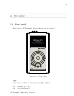
The button for loopback mode control. To switch between layers 1, 2, 3, 4 or
turn loopback off, press this button as many time as needed.
Link speed LED indicators
LED indicators represents link speed.
Table 3.1. Speed LEDs
Speed
LED
LEDs color
10 Mbit/s
100
and
1000
green
100 Mbit/s
100
green
1000 Mbit/s
1000
green
LINK
LED is used to show link state:
•
green — connection is established;
•
off — no connection.
ACT
LED shows the data transmission state:
•
green — data is being transmitted/received at the moment;
•
off — no data is being transmitted or received at the moment.
FDX
LED shows Ethernet interface state:
•
green — full-duplex connection;
•
off — half-duplex connection.
Power
LED lights up when the power supply unit is plugged in.
3.2
External connectors
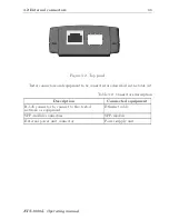
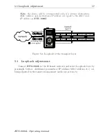
Location of external connectors on the top panel is shown on the figure 3.2.
ETS-1000L. Operating manual
Summary of Contents for ETS-1000L
Page 1: ...ETS 1000L Ethernet Gigabit Ethernet loopback Operating manual Version 1 0 1 2009 Metrotek ...
Page 4: ...4 ETS 1000L Operating manual ...
Page 6: ...6 ETS 1000L Operating manual ...
Page 8: ...8 ETS 1000L Operating manual ...
Page 12: ...12 ETS 1000L Operating manual ...
Page 14: ...14 ETS 1000L Operating manual ...
Page 18: ...18 ETS 1000L Operating manual ...


