10
Overview
•
2
— layer 2 loopback;
•
3
— layer 3 loopback;
•
1+3
— layer 4 loopback.
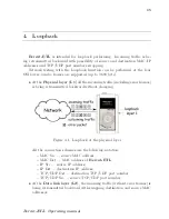
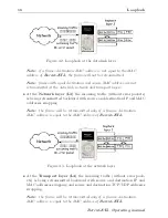
For more details see section 4.
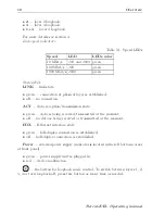
Link speed indicators
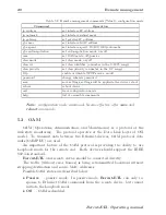
Table 3.1. Speed LEDs
Speed
LED
LEDs color
10 Mbit/s
100
and
1000
green
100 Mbit/s
100
green
1000 Mbit/s
1000
green
State LEDs
LINK
— link state:
•
green — connection at physical layer is established;
•
off — no connection.
ACT
— data reception/transmission state:
•
green — data is being received/transmitted at the moment;
•
off — no data is being received or transmitted at the moment.
FDX
— Ethernet interface state:
•
green — full-duplex connection is established;
•
off — half-duplex connection is established.
Power
— external power supply (indicator is located in the left bottom corner
of front panel):
•
green — power supply unit is plugged in;
•
red — device malfunction.
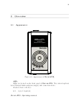
— the button for loopback mode control. To switch between layers 1, 2,
3, 4 or turn loopback off, press this button as many time as needed.
Bercut-ETL. Operating manual
Summary of Contents for Bercut-ETL
Page 1: ...Bercut ETL Ethernet Gigabit Ethernet loopback Operating manual Version 1 1 2 0 2012 Metrotek ...
Page 4: ...4 Bercut ETL Operating manual ...
Page 6: ...6 Bercut ETL Operating manual ...
Page 8: ...8 Bercut ETL Operating manual ...
Page 12: ...12 Bercut ETL Operating manual ...
Page 14: ...14 Bercut ETL Operating manual ...


