


Service functions and error messages
Page 116
Product Manual
“Servo drive DIS-2 310/2 FB FS STO“
Version 4.0
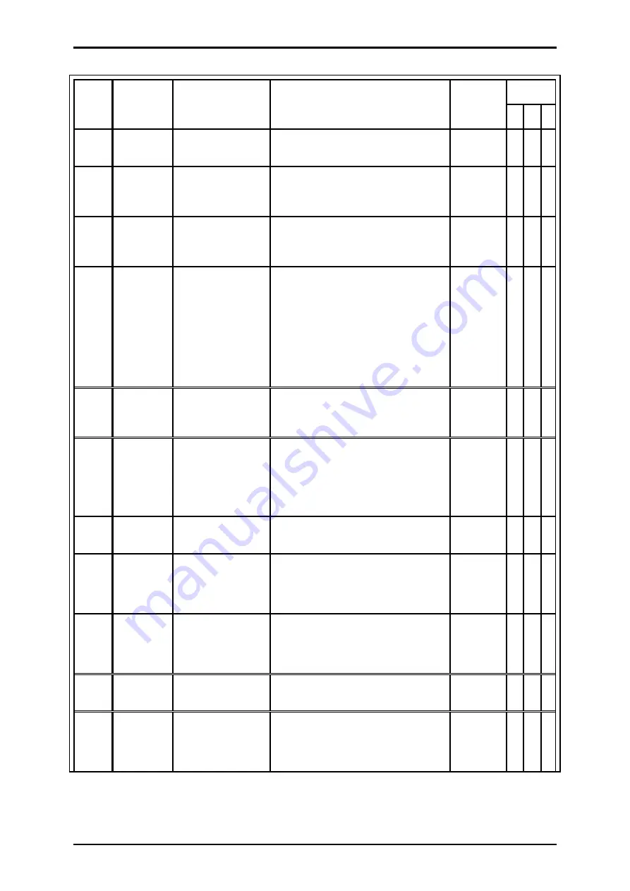
Error
no.
CAN
error code
Meaning
Possible
causes/measures
Response
time
Reaction
C E W
48
--
Error: PROFIBUS
initialisation
Please contact the technical support
team.
< 5 ms
X
53
--
EtherCAT
communication
error
The communication is disturbed:
Check the installation under EMC
aspects.
< 5 ms
X X X
54
--
PROFIBUS
communication
error
The communication is disturbed:
Check the installation under EMC
aspects.
< 5 ms
X X X
55
8100
CAN
communication
error
The communication is disturbed:
Check the installation under EMC
aspects.
Check the baud rate setting.
Check the node number setting. Is
the node used more than once in the
network?
< 5 ms
X X X
56
7510
RS232
communication
error
The communication is disturbed:
Check the installation under EMC
aspects.
< 5 ms
X X X
57
6191
Position data set
error
There is a conflict between the
acceleration and the set travel
speed.
Please contact the technical support
team.
< 5 ms
X
58
6380
Incorrect
operating mode
The operating mode has been
changed while the power stage is on.
< 5 ms
X X X
59
6195
General
arithmetic error
Internal error.
Please contact the technical support
team.
< 5 ms
X
60
6190
Error during the
pre-calculation of
the positioning
Internal error.
Please contact the technical support
team.
< 5 ms
X
61
8762
SYNC message
timeout
A SYNC message has not been
received within the set SYNC time
< 5 ms
X X X
62
6180
Stack overflow
Internal error.
Please contact the technical support
team.
< 5 ms
X


