background image

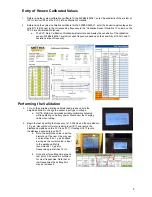
1.

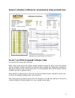
Referencing the system calibration certificate for the 353B04/482A21, enter the sensitivity of the system at
100 Hz into cell D12 on the PVC Field Verification Workbook.

2.

Referencing the system calibration certificate for the 353B04/482A21, enter the deviation percentages into
cells B17 to B35 next to the corresponding frequency in the “Validation Sensor Deviation %” column on the
PVC Field Verification Workbook.

a.

The PVC Field Verification Workbook will calculate and display the sensitivity of the validation
sensor (353B04/482A21 system) at each frequency based upon the sensitivity at 100 Hz and %
deviations at each frequency.

Performing the Validation 

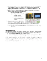
3.

Turn on the portable vibration calibrator and press and hold the
amplitude button to change the sensor input type to voltage.

a.

NOTE: Metrix recommends portable calibrators be tested
while operating on battery power. Disconnect the charging
cable when testing.

4.

Begin the test by setting the frequency to 10,000 Hz and the amplitude to
1.0 g pk. Record the volt meter reading in cell D17 and record the
displayed amplitude on the PVC in cell F17. If testing HI-913 record
the displayed sensitivity in cell E17.

a.

Note: the amplitude value is per the
discretion of the user. One may use
a value other than 1 g pk if desired
as long as the correct value is input
to the workbook. Metrix
recommends 1.0 g pk for
frequencies greater than 10 Hz.

b.

Note: allow for settling time at each
test point, 3-5 seconds is sufficient
for most frequencies. Note that at
low frequencies the settling time
may be increased.

Entry of Known 

C

alibrated Values

5

Summary of Contents for HI-903

Page 1: ...Doc 101060 REV A April 2021 MANUAL KIT HI 903 913 SHAKER CALIBRATION 1...

Page 2: ...SETUP 4 ENTRY OF KNOWN CALIBRATED VALUES 5 PERFORMING THE VALIDATION 5 REVIEWING THE TEST 6 ENTRY OF EQUIPMENT CONDITIONS 7 COMPLETED REPORT 8 SYSTEM CALIBRATION CERTIFICATE 9 TURNING OFF DISPLAYED C...

Page 3: ...s frequencies for models 353B04 accelerometer and 482A21 signal conditioner tested as a system by Metrix A printed copy of this calibration certificate is also included Users will need to provide the...

Page 4: ...ignal conditioner using the supplied 10 32 to BNC male cable 4 Connect the OUTPUT BNC jack of the 482A21 to the BNC T connector a NOTE the BNC T connector is not needed when testing model HI 903 Porta...

Page 5: ...brator and press and hold the amplitude button to change the sensor input type to voltage a NOTE Metrix recommends portable calibrators betested while operating on battery power Disconnect the chargin...

Page 6: ...ponding row in the workbook for each frequency 8 Repeat step 7 for 7 Hz using 0 4 g s pk for the amplitude a Note if using a calibrator with 9100 LF5 firmware repeat step 6 at 5 Hz as well using 0 2 g...

Page 7: ...e date of all test equipment be documented on the test report In cells C40 through F44 users can enterthis data for the accelerometer signal conditioner and volt meter It is also good practice to note...

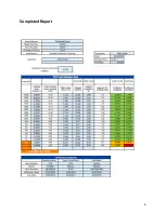
Page 8: ...Completed Report 8...

Page 9: ...rated their calibratorsby following the procedures described in this manual may wish to turn off the displayed date and affix theirown proof of calibration typically a calibration sticker Contact Metr...

Page 10: ...H Y 0KW F VZ 0 8 QGAGR HGDC3G99 N U 4 N 8 QA99R H HCGB99 GG 9F F A H H GD 8C 89F A D D 9A 9 A 4 K 0J J 8 S K607 60J F K607 6JJ 7 5 1 I6 J0K0 1 7 0 J1 C8AAD D 8 D 9 7 6 Z6 6 J 760K 7 2 J1 C8L C C G 9...

Page 11: ...1 Q6 7 R7 J 3 012 1 76 F 7 0Y Z 0Y J 6 8 M67 V 6W FK Z FC 7607 E 6 N6 0 J J QNL R W KZ K6F T0 76 F 7 0Y Z 0Y J 6 8 0 0 X02 V K E K Z6 6 J J 0Y E E YZ7 0Y 8 V 7 K 7 0 V J K7 6W 6 Z6 6 J 7 Z 6F7Z2 6 6 J...

Page 12: ...6F 60J 7 VF W J 0 7Z KF 60 V E F 6 2 X FF 0 J 7 J 7 C 0 XZ KZ Y F67 0 6 6VVF K6 F 2 K7 0 1B 60J 13 E 7Z V 5 J 0E 67 0 Y6 J 0Y K 76 0 F K6F 067 06F d 07 2 1 T6 J0 0 1 0 KZ0 K6F 6 8 0Y 0 0Y 6 0J eIL T4...

Page 13: ...7 K7 5 d V 078 6E 7W YF6 0 60J JW V 7 K7 0 8 0 Z FJ X6 Z J 6E7 K 076K72 WY 0 6 8 0 7Z67 W EF Z 0Y W 7 60J 6E 7W Z X 6 F K67 J KF 7 7Z X 0Y VF6K 2 MZ 0 0Y J 0 7 67b J 0 2 M6 Z K 076 067 J KF 7Z 0Y E C...

Page 14: ...6 656 F6 F K V 7 0 7 V 67 8 J676 656 F6 F K 7W K 7Wb JW06 K 8 7 6VVF K6 F VF 5 V V 7 8 7 VF 5 L J 0Y V V 7 8 Z 760K 7 0 7 KF6 E J 6 J 0Y2 U F K F6 X YZ7 8 J676 656 F6 F 1 5 6 1 0 0 0 _ 4 6K7 5 7W 8 7...

Page 15: ...078 Z 760K 7 Z6 0 6K 7 0Z6F6C 7 0 7 K 7W 4 6 8 O0E 67 0 76 0 E E 0K X 60J 7Z F 7 67 2 K 7 J 6F 7 K 7W 8 S 39 Q46 7R8 _ 3b999 Y Y 078 Z 760K 7 Z6 0 6K 7 J 6F 7 K 7W 4 6 8 O0E 67 0 76 0 E E 0K X 60J 7Z...

Page 16: ...0 E E 0K X 60J 7Z F 7 67 2 P K FF 76Y 0 K 7W C 07 8 0 6F 7 7 0Y J J 0 7 Z X 60W 76Y 0 K EE K7 2 8 D9 P 9D D 7 KF6 E J 6 J 0 656 F6 F 0E 67 02 0 0Y J 07 E 7Z V J K7 V 07 67 F 5 F Y 67 7Z60 d 6F 7 921 J...

Page 17: ...Z V J K7 Z6 0 56F 67 J E 4N4 KZ6 6K7 7 K 60J J 0 7 7 7Z K 7 6 E Z6 6 J X6 7 E J K6 J J 0 7 V KZ6 J E 2 M6 7 E J 8 V E 0 6KK J60K X 7Z F K6F Y F67 0 2 N 076 067 J V6K 6Y 0Y 8 V7W K 076 0 Z FJ 76 0 7 6...

Page 18: ...7 0Y F 5 F 76 F Z J W 4 7F OOOb K7 0 B1B2 21 1 8 P C8 D 9A 4 99A CY89D8 DPH c9 W 7ZWF F 60 b V FW X 7Z U 7ZWF F d 60 DA9B C HC1 9 C G9 F K 0 J J DB1CADCG 3 C 19 F K 0 U 76FF J N VF I V 76 W O0Y J 07...

Page 19: ...1HGD 99CAH 1I 1 5S6 J 7 30 7 H D9 G8 D 9 740b J3 1 b 7 CC a H 8LL YD8 D 9A OL 4 S 8 T 2 OL 4 K 0J J V S 7 L gCB 8 T 2 LKK V67 06F V S 7 QL R C 6 F gCB U 0C 6F 7 OL 4 S M 8 CX YZ7 J 65 6Y K 0K 07 67 0...

Page 20: ...0 K N C V 67 0 60J 5 F V 07l LII C LEE K E NZ K6F 6E 7W 60J I FF 7 0 I 5 07 0l Ic C I 7 07b c 6KK F67 5 60J K 760K l IONN C IZ F VV 0 O05 07 W E NZ K6F 60J NZ K6F 760K l QiR 4 C Qi 607 767 5 R 7 K7 K7...

Page 21: ...s nature this equipment may contain small quantities of substances known to be hazardous to the environment or to human health if released into the environ ment For this reason Waste Electrical and El...

Reviews: