Test Setup
1.
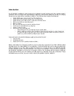
Apply a thin film of silicone grease to the top of the armature on the portable
vibration calibrator.
2.
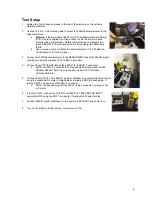
Use the 10-32 to ¼-28 mounting stud to mount the 353B04 accelerometer to the
shaker armature
a.
Warning
: if testing models HI-903 or HI-913 portable vibration calibrator
(PVC) use the supplied mounting wrench to hold the armature while
mounting the accelerometer. Detailed instructions and diagrams are
found inside the PVC manual and on the quick-start guide attached to
the lid.
b.
Use a torque wrench to tighten the accelerometer to 113-225 Newton-
Centimeters (10-20 inch-pounds).
3.
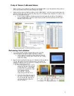
Connect the 353B04 accelerometer to the SENSOR BNC jack of the 482A21 signal
conditioner using the supplied 10-32 to BNC male cable.
4.
Connect the OUTPUT BNC jack of the 482A21 to the BNC T-connector.
a.
NOTE: the BNC T-connector is not needed when testing model HI-903
Portable Shaker Table, it is only used for model HI-913 Portable
Vibration Calibrator
5.
Connect the OUTPUT of the 482A21 signal conditioner to calibrated digital volt meter
using the supplied BNC male to male cable and supplied BNC to banana plug. If
testing HI-913 use one side of the BNC T-connector.
a.
NOTE: the banana plug with the tab on its side connects to ground on the
volt meter
6.
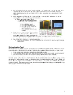
If testing HI-913, connect the OUTPUT of 482A21 to TEST SENSOR INPUT
on model HI-913 using the BNC T-connector. If testing HI-903 skip this step.
7.
Connect 482A21 signal conditioner to line power via DC INPUT and power it on
8.
Turn on the digital voltmeter and set to measure mV AC.
4


