


8
Table 5
aR3!
measurement command sequence
Command
Response
This command reports instantaneous values.
aR3!
a<TAB><waterPotential> <temperature><CR><sensorType><Checksum><CRC>
NOTE: This command does not adhere to the SDI-12 response timing. See
for more information.
Table 6
aR4!
measurement command sequence
Command
Response
This command reports instantaneous values.
aR4!
a<TAB><waterPotential> <temperature><CR><sensorType><Checksum><CRC>
NOTE: This command does not adhere to the SDI-12 response timing. See
for more information.
PARAMETERS
lists the parameters, unit measurement, and a description of the parameters returned in command
responses for TEROS 21.
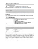
Table 7
Parameter Descriptions
Parameter
Unit
Description
±
—
Positive or negative sign denoting sign of the next value
a
—
SDI-12 address
n
—
Number of measurements (fixed width of 1)
nn
—
Number of measurements with leading zero if necessary (fixed width of 2)
ttt
s
Maximum time measurement will take (fixed width of 3)
<TAB>
—
Tab character
<CR>
—
Carriage return character
<LF>
—
Line feed character
<waterPotential>
kPa
Water potential
<temperature>
°C
Air temperature
<sensorType>
—
ASCII character denoting the sensor type
For TEROS 21, the character is
k
<Checksum>
—
METER serial checksum
<CRC>
—
METER 6-bit CRC
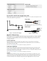
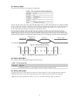
DDI SERIAL COMMUNICATION
The DDI serial communications protocol is ideal for systems that have dedicated serial signaling lines for each
sensor or use a multiplexer to handle multiple sensors. The serial communications are compatible with many
TTL serial implementations that support active-high logic levels using 0 to 3.6 V signal levels. When the sensor
is first powered, it automatically makes measurements of the integrated transducers then outputs a response
over the data line. Systems using this protocol control the sensor excitation to initiate data transfers from
the sensor. This protocol is subject to change as METER improves and expands the line of digital sensors and
data loggers.
NOTE: Out of the factory, all METER sensors start with SDI-12 address
0
and print out the startup string when power cycled.
TEROS 21 will omit the DDI serial startup string when the SDI-12 address is nonzero.