


3
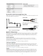
EQUIVALENT CIRCUIT AND CONNECTION TYPES
Refer to
to connect the TEROS 21 to a logger.
provides a low-impedance variant
of the recommended SDI-12 specification.
PIGTAIL CABLE
Ground (bare)
Data (orange)
Power (brown)
NOTE: Sensors manufactured as MPS-6 use white wire for power and
red wire for data output.
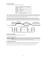
GND
D
ATA
GND
510
R1
R2
100
K
C1
220
PF
L1
10UH
Figure 2 Equivalent circuit diagram
SAFETY PRECAUTIONS
METER sensors are built to the highest standards, but misuse, improper protection, or improper installation
may damage the sensor and possibly void the warranty. Before integrating sensors into a sensor network,
follow the recommended installation instructions and implement safeguards to protect the sensor from
damaging interference.
SURGE CONDITIONS
Sensors have built-in circuitry that protects them against common surge conditions. Installations in
lightning-prone areas, however, require special precautions, especially when sensors are connected to a
well-grounded third-party logger.
Visit
for articles containing more information.
POWER AND GROUNDING
Ensure there is sufficient power to simultaneously support the maximum sensor current drain for all the
sensors on the bus. The sensor protection circuitry may be insufficient if the data logger is improperly
powered or grounded. Refer to the data logger’s installation instructions. Improper grounding may affect the
sensor output as well as sensor performance.
Visit
for articles containing more information.
CABLES
Improperly protected cables can lead to severed cables or disconnected sensors. Cabling issues can be
caused by many factors, including rodent damage, driving over sensor cables, tripping over the cable, not
leaving enough cable slack during installation, or poor sensor wiring connections. To relieve strain on the
connections and prevent loose cabling from being inadvertently snagged, gather and secure the cable
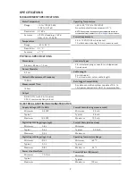
Power Up Time (SDI-12)
Minimum
100 ms
Typical
150 ms
Maximum
200 ms
Measurement Duration
Minimum
Typical
150 ms
Maximum
200 ms
COMPLIANCE
Manufactured under ISO 9001:2015
EM ISO/IEC 17050:2010 (CE Mark)
STEREO CABLE
Ground
Data
Power
Figure 3 Connection types


