


8
OpERATION
2.2.2 CONNECT TO A NON-METER LOGGER
The TEROS 10 can be purchased for use with non-METER (third-party) data loggers. Refer
to the third-party logger manual for details on logger communications, power, and ground
ports. METER has some sample programs for third-party logger setup (see the METER
website).
TEROS 10 sensors typically come configured with stripped and tinned (pigtail) lead wires for
use with screw terminals. Refer to the third-party logger manual for details on wriring.
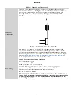
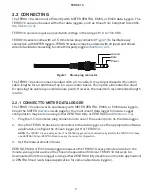
Connect the TEROS 10 wires to the data logger as illustrated in
, with the supply wire
(brown) connected to the excitation, the analog out wire (orange) to an analog input, and the
bare ground wire to ground.
Ground (bare)
Data (orange)
Power (brown)
Figure 2 pigtail wiring
NOTE: Some older adapter cables have the older Decagon wiring scheme where the power supply is white, the digital
out is red, and the bare wire is ground.
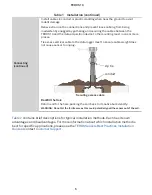
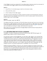
Exc.
H
Analog In
Data Logger
G
L
Analog
Out
Ground
Power
Supply
Figure 3 Wiring diagram
NOTE: The acceptable range of excitation voltages is from 3.0 to 15.0 VDC. To read TEROS 10 sensors with Campbell
Scientific, Inc. data loggers, power the sensors from a switched 12 V port.


