background image

2. Enter a job using the data entry method 

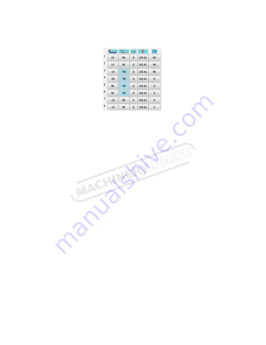
On the left half of the screen is the Data entering area.  


If the profile is displayed, press the mode button to change from the profile display to the 
numerical data block. 

The data block is divided into 5 vertical columns from left to right. 

From left to right is the dimension, angle, trim angle, tool depth and retract columns. 

From top to bottom is the bend numbers of the profile from 1 to the total number of folds plus 
one. This is because any profile has one more side than folds. The last dimension will not have an 
angle. 

1. Press on the top left hand cell, column 1, row 1. On the pop-up keypad, press “0” and “OK” 

This will clear the whole data field. 

2. Enter the first length 50 

3. Enter the first angle 90 

4. Enter the second length 150  

5. Enter the next angle 90 

6. Repeat steps 4&5 until all bends is entered. 

7. Enter the last length 50 

As you go along, the profile is drawn on the right so you can see what it looks like. If a certain 
bend is on the wrong side of the material, change the sign of the angle to a negative for that 
bend. For example if you draw a 2 bend profile as a U shape but you need a Z shape, change the 
angle for bend 2 to negative. This means that the work piece will have to be turned over from 
top to bottom. In the above example bend 1 & 2 is done on the top side (U shape). Change bend 2 
to -90 to change to Z shape.


Page 4

Instruction Manual for PB-170B (S909F)

04/12/2014

Summary of Contents for PB-170B

Page 1: ...INSTRUCTION MANUAL PB 170B Hydraulic CNC Pressbrake 415V 176T x 3200mm S909F Page 1 Instruction Manual for PB 170B S909F 04 12 2014...

Page 2: ...Select correct V width 8 11 Set Material Thickness and width 8 13 Run job without material 9 14 Correct under or overfolding 9 15 Name a Job 10 16 Save a Job 10 17 Open a Job 11 20 Box Mode 12 21 Quic...

Page 3: ...the left half of the main screen is the job edit section that displays either the numerical data block consisting of rows and columns holding job dimensions angles etc above or the actual profile ind...

Page 4: ...1 On the pop up keypad press 0 and OK This will clear the whole data field 2 Enter the first length 50 3 Enter the first angle 90 4 Enter the second length 150 5 Enter the next angle 90 6 Repeat step...

Page 5: ...off Press UNDO to redo a bend Undo Removes last bend Cancel Exit without using current Shape Advanced use of Quickdraw can be found in section 21 When you are happy with the shape press OK and you wi...

Page 6: ...is page a new tool can be drawn up named and saved This is discussed in section 23 To select a different tool from the library press open Select the desired Tool If there are more tools than one page...

Page 7: ...ated named and saved as discussed in section 24 To select a different Die from the library press open Select the desired Die If more Dies than one page use up and down arrow Press cancel then close to...

Page 8: ...uence Press the bend sequence button to go to the bend sequence page Touch on the first bend red dot on profile it will turn grey then the next bend and the next until complete As you go along you can...

Page 9: ...will attempt to find an alternative bend sequence automatically if the default 1 2 3 4 creates a collision If it finds a workable bend sequence it does not mean it will be the best or the fastest A ma...

Page 10: ...ectly Fold up the job with actual material Check angles 14 Correct under or overfolding The third column from the left is the angle trim column If a fold is 5 degrees under enter 5 into the appropriat...

Page 11: ...ottom left is a button that switches between QWERTY style and ABC style Press OK when finished 16 Save a Job Press SAVE and you will be prompted if you want to overwrite the current job Press YES and...

Page 12: ...Autocad SolidEdge SolidWorks Autodesk Inventer etc Press CAD Import to do this and select a job or change directory or select the office computer if utilising a network Select the DXF file and press o...

Page 13: ...d the job to make sure the tooling is correct alter trim angles if necessary and save Now draw up the side view and name it box1 b Edit the sizes on the profile on the Main screen Get the right toolin...

Page 14: ...he job After the last fold on the A side it will automatically switch to the B side on the screen and position You can save this linked job as a complete job by pressing SAVE and LINKED on the window...

Page 15: ...will undo the last action Clear Deletes all data and start again 22 Change Tensile strength correction If large trim values are necessary due to tensile strength enter a percentage tensile correction...

Page 16: ...ners to get the basic shape drawn The end point of the tool should be touched in the same spot as the start point to complete the tool Press UNDO if you make a mistake Press OK to return to the Tool s...

Page 17: ...ockwise direction To enter a side number press on it and it will toggle from 1 to 4 It will not bring up a keypad The last column is the offset which is the distance from the left edge to the centre o...

Page 18: ...this is also when you can access the Commissioning Manager Axis The axis section controls the settings for each axis on the machine Each axis can either be controlled by the plc or a servo drive or it...

Page 19: ...port the PLC and Servo Drives are connected to Baud Rate The Baud Rate specifies the speed of communication on the COM port measured in bps bits per second Data Bits The number of data bits for commun...

Page 20: ...oder pulses to an actual measurement mm per pulse Full Rotation The number of encoder pulses in a full rotation of the Servo Motor Tollerance This is the tolerance of the measurement from the Servo Dr...

Page 21: ...ied address to the Address on the Calibrate Servo Drive screen Next Previous Page There is more than 1 page of settings for Servo Drives this moves between the pages Home Position This specifies if th...

Page 22: ...slow speed in max speed Slow Speed The Slow Speed is the speed of the beam when it is close enough to the material in mm s Home Position The Home Position indicates if the home position of the beam i...

Page 23: ...ions are the limits on the position of the beam in mm Dummy Position This is a secondary Top Bottom Position used to speed up the Pressbrake in mm Easy Calibrate This allows calibration of the positio...

Page 24: ...his is the amount the distance between the top and bottom varies with the force being applied in mm 100t Crowning Max This is the upper limit on the crowning value in mm 100t Crowning Offset This is t...

Page 25: ...re their tools dies and jobs Backup Path This is a path to copy a backup of Fasfold settings and files should something go wrong with the PC Note It is best if this path is removable or remote such as...

Reviews: