Spare parts
ULMS-Series | Version 2.04
27
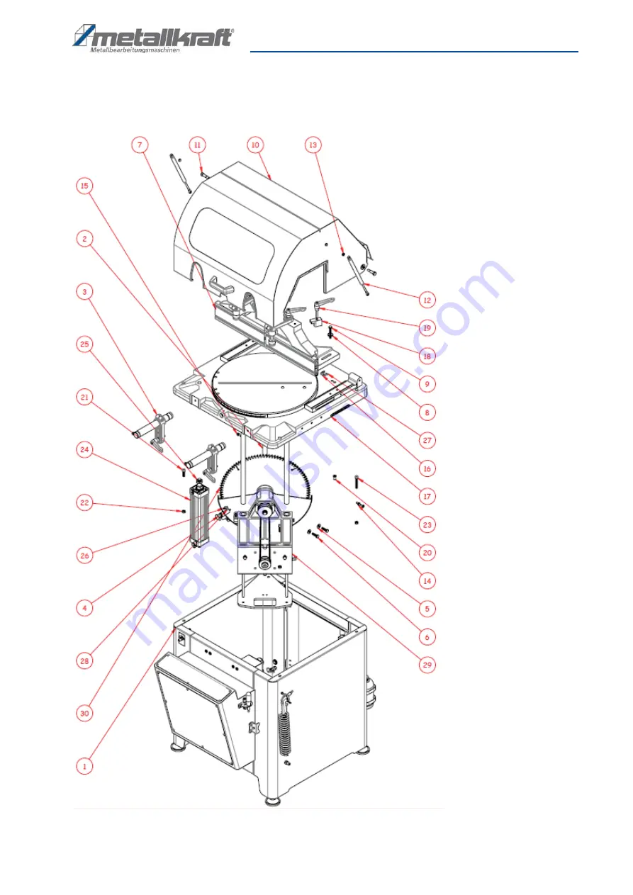
Spare parts drawings ULMS 500
Spare parts drawing 1 - ULMS 500
Fig. 30: Spare parts drawing 1 - ULMS 500
Page 1: ...Instruction Manual ULMS 420 Automatic light alloy metal cutting saw ULMS 500 ULMS 420...
Page 2: ...Use 6 3 1 Reasonably foreseeable Misuse 6 3 2 Residual risks 7 4 Technical Data 7 4 1 Table 7 4 2 Type plate 9 5 Transport Packaging Storage 9 5 1 Delivery and Transport 9 5 2 Packaging 10 5 3 Storag...
Page 3: ...techni cal information Your specialist retailer will be happy to support you with specialist advice and information Germany St rmer Maschinen GmbH Dr Robert Pfleger Str 26 D 96103 Hallstadt Repair se...
Page 4: ...andatory Operators shall also be responsible for maintaining the machine in a technically perfect condition For this rea son the following shall apply Operators shall make sure that the maintenance in...
Page 5: ...er portal 2 6 General safety precautions Note the following Keep the machine and its working environment al ways clean Ensure adequate lighting The Automatic light alloy metal cutting saw must not be...
Page 6: ...As soon as the signs are not clearly visible and compre hensible at first glance the machine must be stopped until new labels have been attached 3 Intended Use The underfloor light metal circular saw...
Page 7: ...rotective goggles 4 Technical Data 4 1 Table Technical Data ULMS 420 ULMS 500 Saw blade speeds rpm 2900 2347 Saw blade diam eter mm 420 500 Saw blade bore mm 30 30 Saw blade thick ness mm 4 0 4 0 Cutt...
Page 8: ...a Cutting diagram and dimensions of the model ULMS 420 Fig 2 Cutting chart ULMS 420 Fig 3 Dimensions Model ULMS 420 Cutting diagram and dimensions of the model ULMS 500 Fig 4 Cutting chart ULMS 500 Fi...
Page 9: ...2000 x 20 x 70 mm Values while working workplace related noise level LvA 92 dB 92 dB Measurement uncertainty K 2 dB 2 dB WARNING Ear protection must be used as the sound level during work may exceed...
Page 10: ...g aids are suitable for recy cling and must always be disposed of using material ba sed recycling systems Packaging materials made of cardboard must be shred ded and recycled as waste paper The foils...
Page 11: ...ay atten tion to carrying capacity and evenness of the subsoil Protruding parts such as support tables stops etc are to be secured if necessary by on site mea sures so that persons are not endangered...
Page 12: ...Close the machine cover 7 3 Electrical Connection Make sure that the mains voltage matches the specified voltage level of the information on the rating plate before connecting your device to the power...
Page 13: ...ew M10x20 with the Allen key When you have completed the above steps the saw is ready for operation 7 5 Replacing the tensioning belt on the ULMS 500 Step 1 Loosen the screws 1 with a wrench as shown...
Page 14: ...e operator and other per sons if they do not adhere to the following rules The operator may not work while under the influ ence of alcohol drugs or medication The operator must not work when he is tir...
Page 15: ...ctivate the cutting process 2 Saw oil adjustment valve 3 MOTOR start 4 EMERGENCY STOP switch 5 Cutting speed valve 6 Hold downs 7 Cutting start Cutting process Step 1 Adjust the clamp height according...
Page 16: ...le turntable with the help of the pin 3 insert the pin into a hole on the turntable to the desired posi tion and block the angular position with the loc king pin Step 2 Check that the locking pin is p...
Page 17: ...gular care and maintenance work must be performed WARNING Risk due to inadequately qualified persons Inadequately qualified persons are unable to assess the risks in case of repairs to the machine thu...
Page 18: ...es and defects resulting from the use of non recommended lubricants DANGER Never use solvents to clean plastic parts or painted surfaces A surface release and consequential da mage may occur DANGER Al...
Page 19: ...Remedy Error at the cutting angles Fuse not calibrated Set the fuse after loosening the screw that holds it in place Turn it to the left or right until it is in the requi red position Then secure the...
Page 20: ...and the health of others Environment and health are endangered by improper disposal Material recycling helps to reduce the consumption of raw materials For more information about recycling this produc...
Page 21: ...lowing drawings are intended to identify the required spare parts in the event of service If applicable submit a copy of the parts drawing including the highlighted components to your authorised retai...
Page 22: ...22 ULMS Series Version 2 04 Spare parts Spare parts drawing 2 ULMS 420 Fig 24 Spare parts drawing 2 ULMS 420...
Page 23: ...Spare parts ULMS Series Version 2 04 23 Spare parts drawing 3 ULMS 420 Fig 25 Spare parts drawing 3 ULMS 420...
Page 24: ...24 ULMS Series Version 2 04 Spare parts Spare parts drawing 4 ULMS 420 Fig 26 Spare parts drawing 4 ULMS 420...
Page 25: ...Spare parts ULMS Series Version 2 04 25 Spare parts drawing 5 ULMS 420 Fig 27 Spare parts drawing 5 ULMS 420 Spare parts drawing 6 ULMS 420 Fig 28 Spare parts drawing 6 ULMS 420...
Page 26: ...26 ULMS Series Version 2 04 Spare parts Spare parts drawing 7 ULMS 420 Fig 29 Spare parts drawing 7 ULMS 420...
Page 27: ...Spare parts ULMS Series Version 2 04 27 Spare parts drawings ULMS 500 Spare parts drawing 1 ULMS 500 Fig 30 Spare parts drawing 1 ULMS 500...
Page 28: ...28 ULMS Series Version 2 04 Spare parts Spare parts drawing 2 ULMS 500 Fig 31 Spare parts drawing 2 ULMS 500...
Page 29: ...Spare parts ULMS Series Version 2 04 29 Spare parts drawing 3 ULMS 500 Fig 32 Spare parts drawing 3 ULMS 500...
Page 30: ...30 ULMS Series Version 2 04 Spare parts Spare parts drawing 4 ULMS 500 Fig 33 Spare parts drawing 4 ULMS 500 Spare parts drawing 5 ULMS 500 Fig 34 Spare parts drawing 5 ULMS 500...
Page 31: ...Spare parts ULMS Series Version 2 04 31 Spare parts drawing 6 ULMS 500 Fig 35 Spare parts drawing 6 ULMS 500...
Page 32: ...32 ULMS Series Version 2 04 Spare parts Spare parts drawing 7 ULMS 500 Fig 36 Spare parts drawing 7 ULMS 500...
Page 33: ...Electrical circuit diagram ULMS Series Version 2 04 33 14 Electrical circuit diagram Electrical circuit diagram ULMS 420 ULMS 500 Fig 37 Electrical circuit diagram ULMS 420 ULMS 500 Power supply...
Page 34: ...34 ULMS Series Version 2 04 Electrical circuit diagram Fig 38 Electrical circuit diagram ULMS 420 ULMS 500 Terminals...
Page 35: ...Electrical circuit diagram ULMS Series Version 2 04 35 Fig 39 Electrical circuit diagram ULMS 420 ULMS 500...
Page 36: ...36 ULMS Series Version 2 04 Electrical circuit diagram Fig 40 Electrical circuit diagram ULMS 420 ULMS 500 Control...
Page 37: ...Electrical circuit diagram ULMS Series Version 2 04 37 Fig 41 Electrical circuit diagram ULMS 420 ULMS 500 Valves...
Page 38: ...d in Class A according to Directive 2014 30 EU This Class A machine is intended for use in commercial operations and environments using a safety distance of 30 m The following harmonized standards wer...
Page 39: ...Notes ULMS Series Version 2 04 39 16 Notes...
Page 40: ...www metallkraft de...