Metallkraft KRBS 101 Instruction Manual Download Page 18

18

KRBS 101 | Version 1.03

Disposal, recycling of used devices

11 Disposal, recycling of used devices

For environmental benefits it is necessary to ensure that 
all components of the machine are only disposed of by 
the provided and allowed means. 

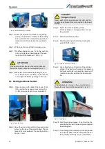
11.1 Decommissioning

Immediately decommission used machines in order to 
avoid later misuse and endangering of the environment 
or of persons.

- Dispose of all environmentally hazardous operating 

materials of the used device.

- If required, disassemble the machine into easy-to-han

-

dle and usable components and parts.

- Supply the machine components and operating materi

-

als to the provided disposal routes.

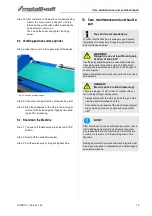
11.2 Disposal of electrical devices

Electrical devices include numerous recyclable materials 
as well as environmentally hazardous components. 

These components must be disposed of separately and 
professionally. In case of doubt, please contact your mu

-

nicipal waste management company. 

For the recycling process, please request the assistance 
of a specialized waste disposal centre if required.

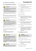
11.3 Disposal of lubricants

The manufacturer of the lubricant makes the disposal in

-

structions for the used lubricants available. If applicable, 
ask for the product-specific data sheets.
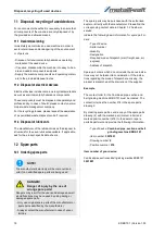
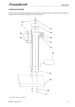
12 Spare parts

12.1 Ordering spare parts

The spare parts may be purchased with the authorised 
dealer or directly with the manufacturer. Please find the 
corresponding contact data in Chapter 1.2 Customer 
service.

Indicate the following basic information for spare part or

-

ders:

- Type of device

- Serial number

- Quantity

- Designation

- Required mode of dispatch (mail, freight, sea, air, 

express)

- Address of dispatch

Spare part orders which do not include the above indica

-

tions may not be taken into consideration. If the indica

-

tions regarding the mode of dispatch are missing, the 
product is dispatched at the discretion of the supplier. 
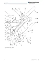
Example

The contact roller for the Combined pipe, section and 
belt grinding machine KRBS 101 must be ordered. The 
contact roller has the number 218 in the spare parts 
drawing 2.

By ordering spare parts, send a copy of the spare parts 
drawing (2) with the marked part (contact roller) and 
marked positon number (218) to the dealer or spare 
parts department and provide the following information:

- Type of device: 

Combined pipe, section and belt 

                             grinding machine KRBS-101

- Item number: 

3921001

- Drawing number: 

2

- Position nummer: 

218

Item number of your device:

Combined pipe, section and belt grinding machine KRBS 101:   

3921001

NOTE!

The manufacturer's warranty will become null and 
void if non admitted spare parts are being used 

DANGER!

Danger of injury by the use of 
wrong spare parts!

Dangers may result for the user and damages as well 
as malfunctions may be caused by using wrong or 
damaged spare parts.

-  Only use original spare parts of the manufacturer or 

spare parts admitted by the manufacturer.

-  Always contact the manufacturer in case of uncer

-

tainties.

Summary of Contents for KRBS 101

Page 1: ...KRBS 101 Instruction Manual KRBS 101 KRBS 101 Combined pipe section and belt grinding machine...

Page 2: ...3 Qualification of personnel 4 2 4 Personal protective equipment 5 2 5 Safety equipment 5 2 6 Safety signs on the machine 5 3 Intended use 6 4 Technical Data 6 4 1 Table 6 4 2 Type Plate 6 5 Transport...

Page 3: ...00 Fax 0951 96555 111 E Mail service stuermer maschinen de Internet www metallkraft de Spare part orders Fax 0951 96555 119 E Mail ersatzteile stuermer maschinen de We are always interested in valuabl...

Page 4: ...the hazards The operator must provide the necessary protec tive equipment to the staff and order the use of the necessary protective equipment in a binding way Furthermore the operating company is re...

Page 5: ...o protect per sons against impairments of safety and health while working The staff has to wear personal protective equip ment while performing different works on and with the Machine which are indica...

Page 6: ...eg sparking of a test piece Proper use also includes compliance with all information in this manual Any use beyond the intended use or oth erwise is considered misuse Misuse The Pipe belt sander must...

Page 7: ...nded over to a recycling center or to the re sponsible disposal company 5 3 Storage The Machine must be stored thoroughly cleaned in a dry clean and frost free environment 6 Description of the device...

Page 8: ...r for 2 pipe Roller for 62 mm pipe Roller for 2 1 2 pipe Roller for 28 mm pipe Extraction unit optional 7 Installation In order to attain good functionality as well as a long du rability of the Machin...

Page 9: ...er 7 2 Set up The four mounting points of the machine should be mar ked and bare holes should be made for anchorages The machine should be rnounted with steel bolts to the floor Installation Site The...

Page 10: ...n the rear work sur face the cover must be closed To do this fold down the work surface after loosening the fixing screws or remove it Then close the cover and tighten the fixing screw Fig 7 Cover on...

Page 11: ...feed travel For the feed travel can be selected from 2 different travel limits For this purpose the feed lever must be screwed to either the front A Fig 11 or the rear hole B at the bottom of the pip...

Page 12: ...be read on the scale Step 4 Tighten the two clamping levers R 8 3 Surface grinding station Step 1 Disconnect the power plug Step 2 Open the cover on the upper side of the device Fig 15 Surface grindin...

Page 13: ...lamping lever Step 10 Check whether the center of the workpiece matches the center of the roller If this is not the case or if a special application is desired adjust the height of the contact roller...

Page 14: ...to the sanding belt may be max 2 mm Step 6 Select the desired operating mode R for belt sander L for pipe grinder L for sur face grinder Step 7 Start the extraction system Step 8 Start the sanding bel...

Page 15: ...hine is always in good operat ing status it is necessary to regularly perform care and maintenance works WARNING Danger in case of insufficient quali fication of the staff Insufficiently qualified per...

Page 16: ...ing the acljuslmenl screw Turn care fully ancl watch how the bell is cloing lf you have rea ched lhe right adjustmenl you should be see ing lhe same distance on both sicles on lhe grincling roller 10...

Page 17: ...e the following information from the machine or from the operating manual so that we can help you in the best possible way Machine model Serial number of the machine Year of manufacture Exact error de...

Page 18: ...anufacturer Please find the corresponding contact data in Chapter 1 2 Customer service Indicate the following basic information for spare part or ders Type of device Serial number Quantity Designation...

Page 19: ...re parts drawings In case of service the following drawings shall help to identify the necessary spare parts If necessary send a copy of the parts drawing with the marked components to your authorised...

Page 20: ...20 KRBS 101 Version 1 03 Spare parts Fig 24 Spare Parts Drawing 2 KRBS 101...

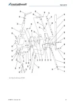
Page 21: ...Spare parts KRBS 101 Version 1 03 21 Fig 25 Spare Parts Drawing 3 KRBS 101...

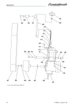
Page 22: ...22 KRBS 101 Version 1 03 Spare parts Fig 26 Spare Parts Drawing 4 KRBS 101...

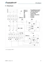
Page 23: ...Wiring Diagram KRBS 101 Version 1 03 23 13 Wiring Diagram Fig 27 Wiring Diagram KRBS 101...

Page 24: ...___ complies with all relevant regulations of the aforementioned directive as well as any other applicable directives subse quently added including the changes applicable at the time the declaration w...

Page 25: ...Notes KRBS 101 Version 1 03 25 15 Notes...

Page 26: ...www metallkraft de...

Reviews: