Metal Works 757161603 Manual Download Page 9

v1.0 22052012

 9

GB

4  Before 

fi

 rst use

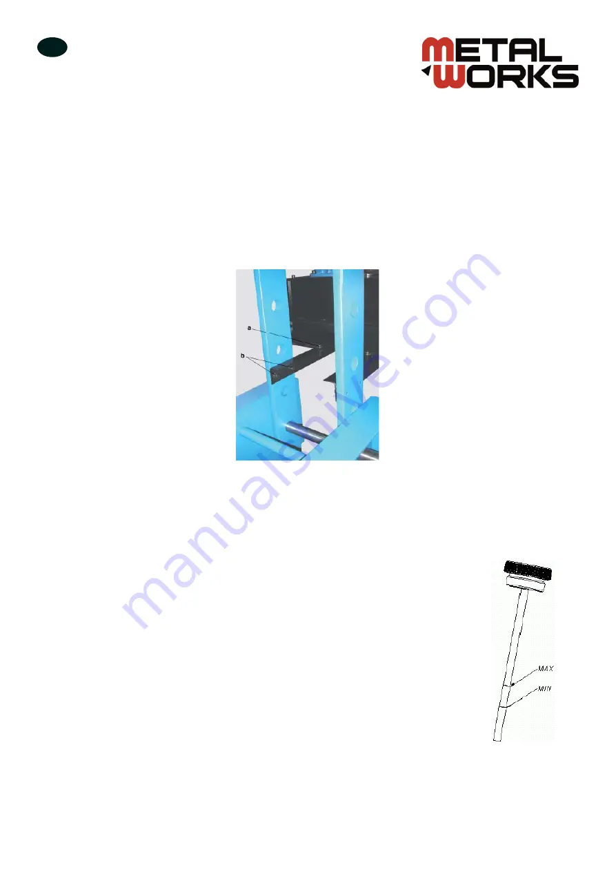
4.1  Mounting the oil tank

After placing the press in a suitable position, unscrew M10 bolts (a) and dismount the oil tank. Next, unscrew 

the M10 bolts (b) from the two supporting brackets and move these brackets from the inner side to the outer 

side of the machine frame. Re

fi

 t the bolts and tighten them. Remove rubber stopper (60 T and 30 T only).

Remember to locate the brackets parallel to each other and perpendicular to the machine frame. Finally, mount 

the oil tank on the brackets and tighten the four bolts (a).


Secure hydraulic hoses using two hose clamps on the upper lateral frame side.

4.2  Filling the oil tank

Remove the 

fi

 ller plug on the hydraulic tank cover. Pour in an appropriate volume of HL 46 

or similar hydraulic oil that is unused and clean. It is important that the oil level reading 

lies between the MIN and MAX marks. The 

fi

 lling operation must be performed when the 

piston is in raised position. This corresponds to a proper position of the suction hose when 

the piston is in its lowest position. Once the tank has been 

fi

 lled, replace the 

fi

 ller plug. A 

drain plug is located at the bottom of the oil tank.

Take care to prevent dirt and water getting inside the oil tank.

copyrighted 

document 

- all 

rights 

reserved 

by 

FBC

Summary of Contents for 757161603

Page 1: ...08 PM60BD2 757161609 PM100V1 757161611 PM100B1 757161612 PM100B2 757161614 PM100B2D 757161615 PM100B2XL 757161616 PM100B2XLD 757161617 PM160V1 757161618 PM160B1 757161619 PM160B2 757161621 PM160B2D 75...

Page 2: ...nection 10 4 4 Direction valve control 10 4 5 Checks before first installation 10 5 Using the press 11 5 1 First use 11 5 2 Regular use 11 5 3 Adjustment of the working table 12 5 4 Emergency stop but...

Page 3: ...age 1 2 Technical data 1 2 1 Single speed press General specification 60 T 100 T 160 T Pressing force kN 588 981 1570 Pressure max bar 235 266 283 Stroke mm 400 400 400 Weight kg 685 955 1575 Electric...

Page 4: ...3 230 3 230 3 230 3 230 3 230 3 230 3 Frequency Hz 50 60 50 60 50 60 50 60 50 60 50 60 50 60 50 60 Rated speed RPM 3000 3000 3000 3000 3000 3000 3000 3000 Insulation Protection IP 54 54 54 54 54 54 54...

Page 5: ...900 900 900 1100 1300 D mm 700 750 750 920 1200 1500 1100 1200 E mm 250 250 250 300 300 300 350 400 F mm 1385 1490 1490 1660 1935 2240 1905 2100 G mm 150 150 150 150 150 150 150 150 H mm 185 191 275 1...

Page 6: ...ment in safe working condition When the machine is in operation do not put your hands into the working area while the piston rod is moving downwards or upwards If an operator accidentally puts his han...

Page 7: ...electrical connections regularly Secure any loose connectors Damaged electrical cables must be replaced immediately by an electrician Never clean electrical equipment with water or similar liquid Bare...

Page 8: ...anders are present in the immediate vicinity of the machine 3 Installation 3 1 Transporting the press This machine can be transported using a pallet truck The use of a forklift truck is also permitted...

Page 9: ...e hydraulic hoses using two hose clamps on the upper lateral frame side 4 2 Filling the oil tank Remove the filler plug on the hydraulic tank cover Pour in an appropriate volume of HL 46 or similar hy...

Page 10: ...quipped with a safety contact 4 4 Direction valve control When the lever is in the middle position the hydraulic oil passes directly through the splitter and the piston stands still When the lever is...

Page 11: ...lignment with the application axis Take care when performing operations on elements that are likely to fly off break especially casting elements and hardened elements or bounce up as a result of the a...

Page 12: ...tubes and attach it to the piston s hooks Then slowly move the piston rod upwards until a small gap appears between the blocking pin and working table pin holes at both sides of the pin Remove the saf...

Page 13: ...djusted left right without moving the workpiece To move this cylinder first unscrew the four M12 fixing bolts using hexagonal socket wrench 10 and move it directly above the pressing point then retigh...

Page 14: ...hange lever is in the WORKING MOTION position If this limit is not observed it can lead to overheating of the hydraulic oil and the operator may suffer burns 6 Maintenance 6 1 Daily maintenance Remove...

Page 15: ...t in motor only version M 1 2 3 4 5 6 7 8 9 No Description QTY 1 Hydraulic cylinder 1 2 Manometer 1 3 Oil tank 1 4 Motor 1 5 Oil pump 1 6 Pressure regulator 1 7 Direction valve 1 8 Non return valve 1...

Page 16: ...tion QTY 1 Hydraulic cylinder 1 2 Manometer 1 3 Oil tank 1 4 Motor 1 5 Oil pump 1 1 6 Oil pump 2 1 7 Pressure regulator 1 8 Direction valve 1 9 Non return valve 1 10 Hand pump 1 11 Cut off valve 1 12...

Page 17: ...v1 0 22052012 17 GB 7 2 Electrical circuit Legend Q1 Starter S1 Emergency stop button c o p y r i g h t e d d o c u m e n t a l l r i g h t s r e s e r v e d b y F B C...

Page 18: ...v1 0 22052012 18 GB Electric circuit with safety screen controlled by a limit switch Depending on version c o p y r i g h t e d d o c u m e n t a l l r i g h t s r e s e r v e d b y F B C...

Page 19: ...e Meet the provisions of the aforementioned directives including any amendments valid at the time of this statement B VYNCKIER VYNCKIER TOOLS SA PM30V2 757161603 PM60V1 757161605 PM60B1 757161606 PM60...

Reviews: