


5
LOCK
WASHER
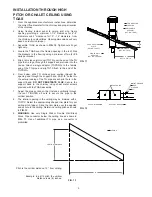
INSTALLATION THROUGH HIGH
PITCH OR CHALET CEILING USING
TGAS
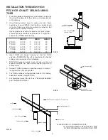
1. From the appliance manufacturer’s instructions, determine
the correct flue diameter for the chimney and proper location
of the chimney.
2. Using framing lumber equal to ceiling joist size, frame
opening providing a minimum 1-1/2” clearance for 6”-8”
diameters and 2” clearance for 10” - 12” diameters from
the chimney to combustibles. Opening dimensions will vary
based on roof pitch (slope).
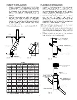
3. Assemble TGAS as shown in
FIG 12
. Tighten nuts finger
tight only.
4. Locate the TGAS over the framed opening in the roof. Nail
the brackets to the framing using a minimum of two (2) #8
nails per bracket.
5. Slip a trim sleeve joint cover (TGTS) over the end of the TG
pipe that is to go through the support and protrude into the
house. Attach a single adaptor (TGPSWA) to the female
end of the TG pipe and slip TGTS flush to the end of the
TGPSWA.
6. From below, slide TG chimney pipe section through the
opening and through the support band. Drill 1/8” holes into
the exterior casing of the TG pipe at each pilot hole in the
support band.
DO NOT PENETRATE FLUE.
Secure the
support band to the chimney using sheet metal screws
provided with the TGAS assembly.
7. Adjust the pipe section so that it stands vertically through
the roof. TIGHTEN all nuts to secure the pipe in the
vertical position.
8. The interior opening in the ceiling may be trimmed with a
TGPCP. Select the appropriately shaped trim plate for your
ceiling pitch (slope). Slide the trim plate over the opening
and secure to the ceiling. Determine ceiling pitch as shown
in
FIG. 13
.
9.
WARNING:
Use only Single Wall or Double Wall Black
Stove Pipe connector below the ceiling line as shown in
FIG. 11
. Use of additional TG pipe as a connector is
prohibited.
L944 FIG12
L944 FIG13
STORM COLLAR
FLASHING
ADJUSTABLE
SUPPORT
(CAT. NO. TGAS)
TRIM SLEEVE
(CAT. NO. TGTS)
A
REF. TO FIG. 10
PITCHED CEILING
PLATE
(CAT. NO. TGPCP)
FIG. 11
PILOT HOLES
NUT
FLAT WASHER
SUPPORT BRACKET
SUPPORT BAND
FIG. 12
VERTICAL DISTANCE
12”
CEILING
Pitch is the vertical distance, 12 “ from ceiling.
Example: In a 6/12 pitch, the vertical
distance is six (6) inches.
FIG. 13
SINGLE WALL
ADAPTER
(CAT. NO. TGPSWA)
6” MIN.


