Metal Fab Temp/Guard Installation And Maintenance Instructions Manual Download Page 4

4

HIGH PITCH OR 

CHALET CEILING

ROOF SUPPORT 

(CAT. NO. TGRS)

(4) NAILS PER SIDE

TEMP GUARD 
ADAPTOR INCLUDED

FIG. 8

FIG. 9

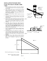
INSTALLATION THROUGH HIGH 
PITCH OR CHALET CEILING USING 
TGRS

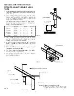
1.  From the appliance manufacturer’s instructions, determine


the correct flue diameter for the chimney and proper location


of the chimney.

2.  Using  framing  lumber  equal  to  ceiling  joist  size,  frame


opening as shown in 

FIG. 9

. Framing that is perpendicular 


to  the  roof  joists  must  also  be  vertically  mounted  so  that


support can be installed vertically.


Opening dimensions will vary based on roof pitch (slope).  


Framed openings should be approximately ¼” larger than  


support. The TGRS dimensions are:

LENGTH

WIDTH

HEIGHT

6”TGRS

12-7/16”

X

12-7/16”

29”

7”TGRS

13-7/16”

X

13-7/16”

29”

8”TGRS

14-7/16”

X

14-7/16”

29”

10”TGRS

16-7/16”

X

16-7/16”

29”

12”TGRS

18-7/16”

X

18-7/16”

29”

3.  Insert  TGRS  into  framed  opening  so  that  the  TGRS


extends  a MINIMUM of three (3) inches below the finished


ceiling on the lower side of the installation.

4.  With  TGRS  properly  located,  mark  roof  slope  on  the  roof


support (See 

FIG. 10.

), Remove from opening and trim off


excess metal.

5.  Reinsert TGRS and secure in position using a minimum 1”  


roofing nail, four (4) each per side.

6.  The TGRS contains an integral starter collar for TG chimney.


Attach first section of pipe to TGRS.

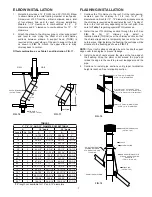
7.  Continue pipe through the roof. See “Flashing Installation”


and “Termination” sections.

FIG. 10

JOIST

SHEET ROCK

ROOF SUPPORT

CONNECTOR PIPE

MARK SLOPE AND TRIM OFF THIS PORTION

WALL STUDS

SHEET ROCK

3” MINIMUM LENGTH


18” FROM SINGLEWALL BLACK STOVE  PIPE 


  6” FROM DOUBLEWALL BLACK STOVE PIPE

A

A=CLEARANCE  TO  COMBUSTIBLES  OF:      

Summary of Contents for Temp/Guard

Page 1: ...NT FOR OIL OR COAL BURNING APPLIANCES OUTSIDE THE ENVELOPE OF THE BUILDING USE ONLY PIPE WITH STAINLESS STEEL CASING ALSO USE FLASHING OR STORM COLLARS CONSTRUCTED OF STAINLESS STEEL OR ALUMINUM OPERA...

Page 2: ...g in the ceiling using FIG 1 and Table 1 6 Install Temp Guard chimney sections starting at the TGCSP Secure the sections by pushing together and twisting until stop locked See FIG 3a Additional chimne...

Page 3: ...wall support to maintain 2 clearance to combustibles TIGHTEN CLAMPS 10 Slip a trim sleeve joint cover TGTS over the male end of TG pipe that is to reach through the wall firestop to the tee Attach sin...

Page 4: ...16 29 7 TGRS 13 7 16 X 13 7 16 29 8 TGRS 14 7 16 X 14 7 16 29 10 TGRS 16 7 16 X 16 7 16 29 12 TGRS 18 7 16 X 18 7 16 29 3 Insert TGRS into framed opening so that the TGRS extends a MINIMUM of three 3...

Page 5: ...support band Drill 1 8 holes into the exterior casing of the TG pipe at each pilot hole in the support band DO NOT PENETRATE FLUE Secure the support band to the chimney using sheet metal screws provid...

Page 6: ...has set up tighten the nuts onto the bolts Proceed to stack Metal Fab chimney pipe TG on the anchor plate 6 See Flashing Instructions and Termination sections NOTE Existing masonry flues may be exten...

Page 7: ...ameters L944 FIG17 C B A FIG 17 1 1 2 FOR 6 8 DIAMETERS 2 FOR 10 12 DIAMETERS DIM WILL VARY WITH ROOF PITCH Must maintain 1 1 2 for 6 8 diameters 2 for 10 12 diameters to combustibles 1 1 2 FOR 6 8 DI...

Page 8: ...he interest of safety and do not ensure smoke free operation Trees buildings adjoining roof lines adverse wind conditions etc may create need for a taller chimney should smoking occur Additional suppo...

Reviews: