ENGLISH
24
Low auxiliary fence
:
– for cutting thin stock.
Length adjustment
:
– for adjusting the rip fence for the
workpiece length.
Using the scale stamped on the saw ta-
ble
you can set the distance from
the rip fence to the saw blade.
If you do not need the push stick you
can fasten it via the clip
to the rip
fence profile for easy access at all
times.
A
Danger!
Modifications to the saw or use of
parts not tested and released by the
manufacturer can lead to unforeseen
damage during operation!
– Use only the parts supplied as
standard delivery.
– Do not change any parts.
If you follow these instructions you will
have no problems with the set-up:
•
Read the instructions for each step
before executing it.
•
Lay out the parts required for each
work step.
6.1
Setting up the machine
•
Place the machine on a firm, level
floor.
•
To align the table surface horizon-
tally, compensate for unevenness or
slippery floor surfaces using suita-
ble materials. Then check that the
machine is stable.
•
The area around the circular saw
should be free of obstacles and trip-
ping hazards.
•
Ensure there is sufficient space to
handle larger workpieces.
For maximum upright stability the saw
can be bolted to the floor:
1. Place the fully assembled saw at a
suitable site and mark the bore
holes on the floor.
2. Move saw aside and drill the holes.
3. Align saw with the holes and bolt to
the floor.
A
Risk of injury by inhaling
wood dust!
Always connect a dust collector to
the saw if operating the saw in
closed rooms.
6.2
Table extension
3
Note:
The table extension supports must be
firmly screwed to the saw table.
Screwing on the table extension
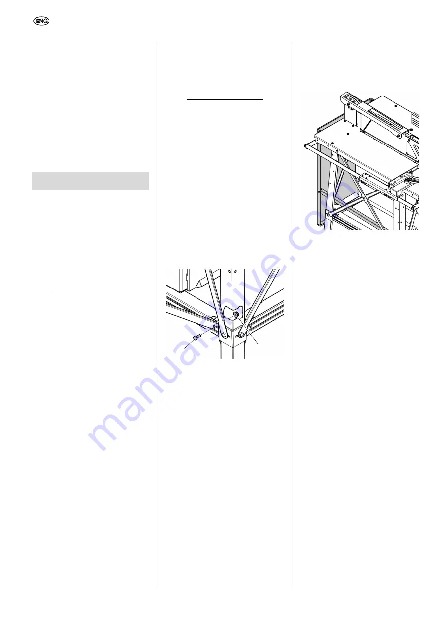
1. Stick the angled ends of the sup-
ports into the slots in the cross-
struts on the rear of the saw and
push them outwards.
2. Screw the supports to the struts us-
and one hexagon nut
for each
as illustrated.
Tightening the screwed connections
Check all screwed connections of the
saw. Tighten the screwed connections
hand-tight using a suitable tool.
When tightening the screws, bear in
mind the following:
– The machine must be secure and
horizontal after the screws have
been tightened.
Aligning the table extension
– The surfaces of the table extension
and saw table must both be in the
same plane.
Swinging the table extension down
1. Unscrew and remove the hexagon
head screws
on both ends of
the supports. Store the screws and
nuts.
2. Slide the lower ends of the supports
towards each other.
3. Unhook the supports and carefully
swing the table extension down as
illustrated. Set the table extension
supports down on the lower cross-
struts of the saw table.
6.3
Mains connection
Mains cable
– Make sure that the mains cable is
out of the way so that it does not in-
terfere with the work and cannot be
damaged.
– Protect mains cable from heat, ag-
gressive liquids and sharp edges.
– Connect the machine to the power
supply using a suitable plug connec-
tion.
– Use only rubber-insulated extension
cables with sufficient cross sections
(see 'Technical Data').
– Do not pull on mains cord to unplug.
B
High voltage!
Operate saw in dry environment on-
ly.
Operate saw only on a power source
matching the following requirements
(see also 'Technical Data'):
– Outlets must be properly installed,
earthed and tested.
– Outlets must have neutral wires for
3-phase DC.
– The supply voltage and frequency
must match the data given on the
machine's nameplate.
– Protection against electric shock by
a residual current device (RCD) of
30 mA sensitivity.
6.
Set-up
45
46
Summary of Contents for BKS 400 Plus
Page 4: ......


