


IMO 10/19
4
IMO-215 EN
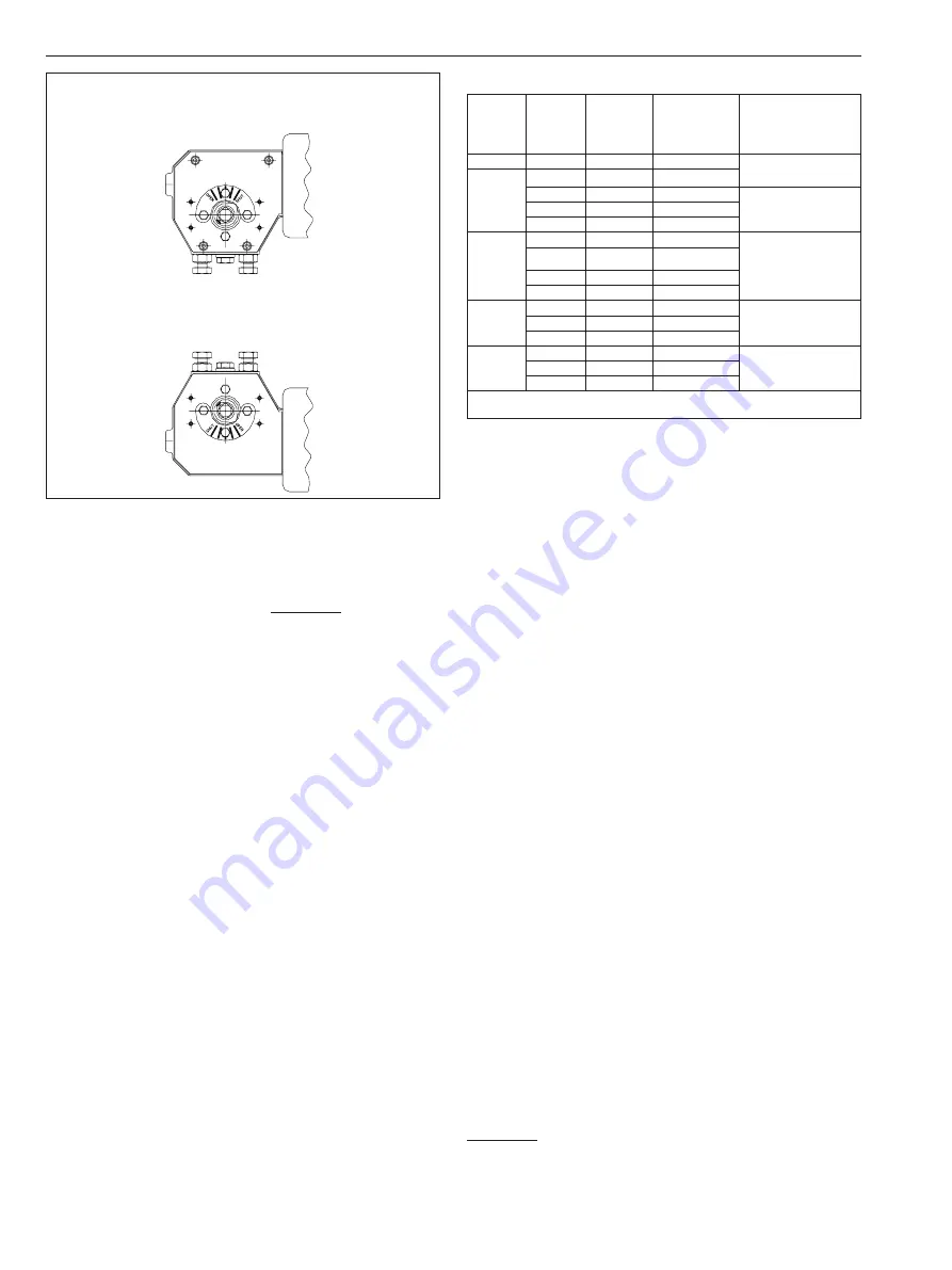
SPRING-TO-CLOSE
In this mode, the actuator will cycle clockwise
to close upon loss of pressure
SPRING-TO-OPEN
In this mode, the actuator will cycle counterclockwise
to open upon loss of pressure
Figure 2.
3. Mount the actuator to the valve following the directions
in the AMI (Actuator Mounting Instructions) or valve IMO.
4. Connect a regulated air supply to the 3/8" NPT fitting
in the diaphragm casing (15). CAUTION: The maximum
operating pressure is 100 psi (6.9 BAR).
5. Adjust the stop screws (19) by releasing the jam nut (23)
and turning. Stops can only be adjusted when driver
arm (3) is off the stop screws being adjusted. (Maximum
rotation adjustment ±5˚.) Be sure to retighten jam nut (23).
2.1
Operation
The operating pressure, output torque and drive type
is determined by the actuator designation. Maximum
operating pressure is 100 psi (6.9 BAR). (See Table 2)
Actuator designation example: QPX4C/K40 is a series QPX4
spring diaphragm actuator that has a 60 psi (4.1 BAR) spring,
an end of air pressure stroke output torque of 200 FT•LBS
(272 N•m) and uses a 40 mm female key to drive the valve.
Before operating make sure all tapped holes in the body
which are not being used are resealed with fasteners.
3.
MAINTENANCE
Although Metso’s
Jamesbury
actuators are designed to work
under severe conditions, proper preventative maintenance
can significantly help to prevent unplanned downtime and
in real terms reduce the total cost of ownership. Metso
recommends inspecting actuators at least every five (5)
years. The inspection and maintenance frequency depends
on the actual application and process condition.
Before working on a
Quadra-Powr
X actuator, note that all
fasteners except socket head shoulder screw (8) and hex
head cap screw (88, on QPX4 & QPX5) are metric.
Table 2
Actuator
Series
Spring
Version
Operating
Pressure
in psi
(BAR)
End of Spring
Stroke
Torque in
FT•LBS (N•m)
Drive Type
QPX1
C
60 (4.1)
25 (34)
K15 - 15 mm Keyed
M - 9/16” Square
QPX2
A**
20* (1.4)
11 (15)
B
40 (2.8)
38 (52)
K20 - 20 mm Keyed
M - 9/16” Square
C
60 (4.1)
57 (77)
D
80 (5.5)
74 (100)
QPX3
A
20* (1.4)
26 (35)
K35 - 35 mm Keyed
M - 3/4” Square
B
40 (2.8)
76 (103)
C
60 (4.1)
114 (155)
D
80 (5.5)
146 (198)
QPX4
B
40 (2.8)
153 (207)
K40 - 40 mm Keyed
M - 1” Square
C
60 (4.1)
229 (310)
D
80 (5.5)
294 (399)
QPX5
B
40 (2.8)
305 (414)
K40 - 40 mm Keyed
M - 1” Square
C
60 (4.1)
458 (621)
D
80 (5.5)
587 (796)
* For Direct Control Application
** QPX2A only available with QPX1 drive type options.
Under normal operating conditions the actuator requires
only periodic observation to ensure proper adjustment.
Standard replacement of “soft” parts in
Quadra-Powr
X
actuators consists of items numbered 6, 14, 31, 62 and 64.
See REPAIR KITS/SPARE PARTS Section.
1. When replacing the diaphragm use caution and be sure
the air supply is disconnected. Back off nuts (29) from
the hex head screws (27), holding the diaphragm casing
and spring housing together until the nuts are flush
with the hex head screw ends. Do not remove the nuts
completely from the hex head screws. If tension still
exists on the hex head screws, then the spring package
is not properly contained. Stop disassembly: retighten
nuts and return the actuator to the factory. If the spring
package proves to be intact remove the nuts (29) and
remove the hex head screws (27).
2. Lift off diaphragm casing (15). Remove hex head cap screw
(88) and retaining washer (89). Remove diaphragm (14).
3. Inspect the inside of both the diaphragm casing (15) and
the spring housing (32) for any rough spots or foreign
matter which may cause abrasion to the diaphragm.
4. Place the new diaphragm (14) on the diaphragm retainer
(10). Do not pinch or stretch the diaphragm. Attach
with washer (89) and cap screw (88). Tighten to value in
(Table 3) keeping spring housing (32) holes aligned with
diaphragm (14) holes. Place the diaphragm casing (15)
on the spring housing (32) and line up all the holes.
5. Insert hex head screws (27) in all holes. Do not force the
hex head screws through the diaphragm. Install nuts
(29) on screws and tighten uniformly using the standard
practice of tightening diametrically opposite bolts in
sequence with the torque requirements from (Table 3).
3.1
Disassembly
When disassembly of the actuator is required for
maintenance, remove the actuator to a clean well lit area.
Handling of the actuator is accomplished by using lifting
straps. See Section 1.2.
CAUTION: Disconnect any pneumatic or electrical supplies,
and vent any air pressure in the actuator before attempting
any disassembly.


