Messoa PTZ900 Quick Start Manual Download Page 4

3

English

Table 1 - 1: Pictorial Index Definition

Index # Name

Descriptions

1

Default Button

Press via paperclip or thin object to restore to the factory defaults by pressing and holding 
the button for 5 seconds.

2

SD Card Slot

Insert SDHC/SDXC card for file storage. (SD card sold separately)

3

Reset Button

Press via paperclip or thin object to reboot the unit.

4

Rear Lid

Remove rear lid for more I/O connectors on the back of camera.

5

Power Indicator

Lights on when powering on the camera.

6

Power Terminal

DC12V/AC24V, red port: power +/ white port: power –/ black port: GND. Make sure to 
connect the power connector to correct ports (+ and –) when the power supply is DC12V.

7

Safety Wire Hook

Connect one end of safety wire here for preventing from falling off.

8

R J - 4 5   E t h e r n e t 
Connector/PoE

To insert the RJ-45 cable for network connection along with PoE (Power over Ethernet) 
capability.
Ethernet Activity LED

Amber flashing indicates data is being transmitted / received 
by the unit.

Ethernet Link LED

Solid green light stands for a live connection is established.

9

Video Out

To connect monitor out cable for video output signal.

10

Audio Input

Connecting to an auxiliary microphone to record ambient audio from the camera.

Audio Output

Connecting to a speaker that transmits voice from control end.

11

Alarm Output

Connecting to a device that responds to alarm signals.

Alarm Input

Connecting to a device that triggers alarm signals.

Caution

Note

To avoid damage to the unit, never connect more than one type of power supply (PoE IEEE802.3 Ethernet 
Class 0 or DC 12V/ AC24V power plug) at the same time. If using PoE, this camera is to be connecting only 
to PoE networks without routing to heterogeneous devices.

Power supply terminal/adaptor for IO connectors and field wiring should comply with the Class 2 Circuit 
standard for ensuring safety from electrical fires and providing acceptable protection against electrical 
shock.

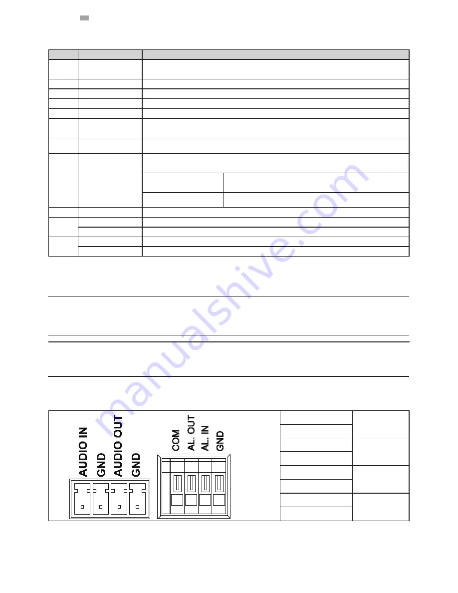
Table 1 - 2: I/O Connectors Definition

AUDIO IN

Audio in

GND

AUDIO OUT

Audio out

GND

COM

Alarm out

AL. OUT

AL. IN

Alarm in

GND


Summary of Contents for PTZ900

Page 1: ...Network Camera Quick Start Guide 201407 900 A1 PTZ900...

Page 2: ...1 English 1 Product Overview 1 1 Physical Characteristics Figure 1 1 Physical Dimensions without Ceiling Bracket Figure 1 2 Physical Dimensions with Ceiling Bracket...

Page 3: ...2 English Figure 1 3 Pictorial Index...

Page 4: ...ndicates data is being transmitted received by the unit Ethernet Link LED Solid green light stands for a live connection is established 9 Video Out To connect monitor out cable for video output signal...

Page 5: ...might help you complete the installation a drill screwdrivers wire cutters 2 2 1 Checking Appearance When first unboxing please check whether if there is any visible damage to appearance of the unit...

Page 6: ...ponding to the 3 indicated positions for plastic anchors supplied 2 Please then insert the 3 plastic anchors supplied into the 3 drilled holes on the mounting surface 3 The Cable Channel indicated is...

Page 7: ...rectly use 3 screws to attach the bracket to the ceiling until the bracket is tightened safely Caution Be sure to tighten the screw nuts firmly as the following figure shown Figure 2 2 Attach Bracket...

Page 8: ...of the camera to ensure the camera won t fall down 3 Push the hooks x4 of the ceiling bracket into the hook holes x4 of the camera bottom Figure 2 4 Attach Safety Wire with Camera and Bracket Figure...

Page 9: ...and then push the camera body forward Finally the camera is assembled to the ceiling bracket firmly 5 Finally connect to the power supply and the network cable to the connectors on the back of camera...

Page 10: ...the camera body backward by the other hand to fully dismantle the camera from the ceiling bracket Figure 2 8 Push Hook to detach Camera from Bracket Warning Depending on the mounting surface you may...

Page 11: ...t connection capability through the Ethernet cable Caution Never connect more than one type of power supplies at the same time to avoid damage to the unit If using DC supply make sure the polarity is...

Page 12: ...GHz or equivalent RAM 1 GB Display NVIDIA GeForce 6 Series or ATI Mobility Radeon 9500 System Software Operating System Microsoft Windows Vista or Windows 7 Browser Microsoft Internet Explorer 9 or ab...

Page 13: ...computer 1 Make sure the unit and your computer are in the same subnet 2 Check whether if the networking available between the unit and the computer by executing ping the default IP address To do thi...

Page 14: ...ookies Click OK 2 When a proxy server is used click Internet Options on the Tools menus of Internet Explorer select Connect tab click LAN button and set proxy server 3 Change Security in Internet opti...

Page 15: ...follows Download signed ActiveX controls Prompt recommended Download unsigned ActiveX controls Prompt Initialize and script ActiveX not marked as safe for scripting Prompt Figure 2 12 Security Setting...

Page 16: ...ipting Enable Figure 2 14 Security Setting 4 4 Press OK to save the settings Close all Microsoft Internet Explorer Windows and restart a new window This will allow the new settings taking effect Type...

Page 17: ...settings If you have multiple cameras connected to your local network locate the MAC address on the camera to distinguish the target camera from others 5 Configure the following settings as needed NAM...

Reviews: