


Revision 2.2
Page 4 of 14
www.resourcedm.com
Mercury Switch User Guide
Warning
Please Note
The specifications of the product detailed on this
Set-Up Guide may change without notice. RDM
Ltd. shall not be liable for errors or for incidental
or consequential damages, directly and indirectly,
in connection with the furnishing, performance or
misuse of this product or document.
Ensure that all power is
switched off before
installing or maintaining
this product
Connection to Mercury Controllers:
Using a standard CAT5 patch lead, connect the serial output of the RDM Controller to one of the RS232 ports of the Mercury Switch.
RS232 Lead Lengths
RS232 patch lead maximum length must not exceed 15 metres. (Ports 1 - 10)
The 3-character address that will be seen on the system front end is determined by the position of the two Network ID rotary switches
and the port the controller has been connected to, unless the connected controller has its own network ID rotary switches, in which case
the controller ID will override the switch settings.
Connection to other IP equipment
Use a standard CAT5 patch lead to connect other IP equipment to the Mercury Switch (such as a Futura IP module) into the 10/100 Base
T ports 1, 2 or 3.
Connection to another Mercury Hub/Switch or Other Ethernet Hub/switch
Use a standard CAT5 patch lead from any of the 3 10/100 Base T ports into any of the 3 10/100 Base T ports on the upstream Mercury
Switch. The 3 10/100 Base T ports are all self configuring.
Connection to a Data Manager/Director
Use a standard CAT5 patch lead and connect the Data Manager or Data Director to one of the 3 10 Base T ports.
10/100 Base T connectors
The three 10/100
Base T connectors have 2 LED’s adjacent to them: The green LED; when static, indicates that the connection to the
device is good, the green LED then flickers when data is being transmitted.
When the amber LED is permanently on it indicates that the connection is full duplex and if there is an error or fault on that channel the
LED flickers.
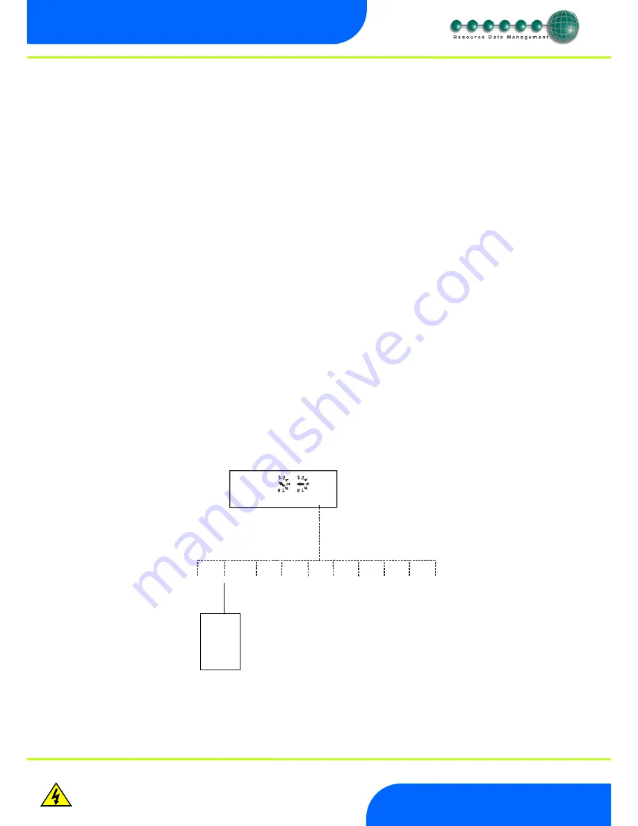
Network ID
The 3-character network ID is made up from the positions of the 2 rotary switches and the RS232 connector number. We recommend
that the 2 rotary switches are set to the Bay number and that the case sections are plugged into their corresponding RS232 port
numbers.
E.g. Bay 10 case 2:
The 2 rotary switches set to "1" and "0", controller plugged into port 2. The ID then is seen as "102" at the system front end.
Note that case number 10 would plug into RS232 port 0 (right most port) and come through as "100".
ID for equipment with rotary switches.
For RDM products that use the 3 rotary switches for the network ID (such as Mercury Power tray), the ID will follow what is set on the
controller local switches and
NOT
the port position on the Switch.
1
9
0
1
9
0
NETWORK ID
1
2
3
Vdc
1 2 3 4 5 6 7 8 9 0
Controller
at position 2


