background image

25

Chapter 3: BIOS Setup Utility

Chapter 3 BIOS Setup Utility

Introduction

The BIOS Setup Utility records settings and information of your computer, such
as date and time, the type of hardware installed, and various configuration
settings. Your computer applies the information to initialize all the components
when booting up and basic functions of coordination between system compo-
nents.

If the Setup Utility configuration is incorrect, it may cause the system to
malfunction. It can even stop your computer booting properly. If it happens,
you can use the clear CMOS jumper to clear the CMOS memory which has
stored the configuration information; or you can hold down the 

Page Up

 key

while rebooting your computer. Holding down the 

Page Up

 key also clears the

setup information.

You can run the setup utility and manually change the configuration. You might
need to do this to configure some hardware installed in or connected to the
motherboard, such as the CPU, system memory, disk drives, etc.

Running the Setup Utility

Every time you start your computer, a message appears on the screen before the
operating system loading that prompts you to “

Hit <DEL>if you want to run

SETUP

”.  Whenever you see this message, press the 

Delete

 key, and the Main

menu page of the Setup Utility appears on your monitor. If you manually clear
CMOS, you need to press the 

F1

 key that enters the Main menu page of the

Setup Utility.

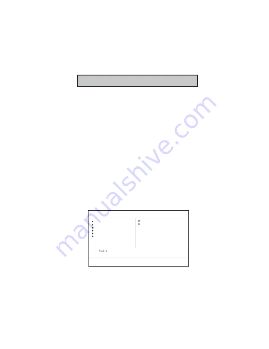
CMOS SETUP UTILITY – Copyright (C) 1985-2004, American Megatrends, Inc

Standards COMOS setup for changing time, date, hard disk type, etc.

V02.56  (C) 1985-2004, American Megatrends, Inc.

                 : Move   +/-/: Value   Enter: Select   F1: General Help   Esc: Exit
  F9: Optimized Settings      F10: Save

Standard CMOS Setup
Advanced Setup
Features Setup
Power Management Setup
PCI / Plug and Play Setup
BIOS Security Features

CPU PnP Setup
Hardware Monitor
Load Optimal Defaults
Save Changes and Exit
Discard Changes and Exit

Summary of Contents for PI865GVM7 Series

Page 1: ...tel Corporation Microsoft MS DOS and Windows NT 2000 XP are registered trademarks of Microsoft Corporation AMI is a trademark of American Megatrends Inc It has been acknowledged that other brands or p...

Page 2: ...cting Optional Devices 14 Install Other Devices 16 Expansion Slots 18 Chapter 3 BIOS Setup Utility 22 Introduction 22 Running the Setup Utility 22 Standard CMOS Setup Page 23 Advanced Setup Page 24 Fe...

Page 3: ...crosoft Therefore it might happen under Windows XP that a dialogue box shown as below pop out warning you this software has not passed Windows Logo testing to verify its compatibility with Windows XP...

Page 4: ...d one VGA port one serial port one parallel port one LAN port optional three audio jacks for micropone line in and line out and four back panel USB 2 0 ports In addition onboard USB headers provide ex...

Page 5: ...rates up to 1 5 Gb s 150 MB s Integrated IDE Controller Ultra ATA 100 66 33 BMIDE and PIO modes USB 2 0 Includes 4 UHCI Host Controllers increasing the number of external ports to eight AC Link for Au...

Page 6: ...grated Fast Ethernet MAC physical chip and transceiver onto a single chip Supports 10Mb s and 100Mb s N way auto negotiation Support ACPI power management Full Duplex Flow Control IEEE 802 3x and Half...

Page 7: ...re items are subject to change without notification Package Contents Your motherboard package ships with the following items The motherboard The User s Guide One diskette drive ribbon cable optional O...

Page 8: ...ctly Install this motherboard in a system chassis case Connect any extension brackets or cables to headers connectors on the motherboard Install peripheral devices and make the appropriate connections...

Page 9: ...6 Motherboard User s Guide Motherboard Components 4 6 7 9 10 12 15 14 16 13 3 18 19 20 1 2 5 22 21 8 1 1 17 IO PORTS...

Page 10: ...ctor 7 IDE1 Primary IDE connector 8 IDE2 Secondary IDE connector 9 DIMM1 DIMM3 184 pin DDR SDRAM sockets Support Dual Channel DDR400 10 DIMM2 184 pin DDR SDRAM sockets 11 JP1 Clear CMOS jumper 12 SATA...

Page 11: ...parallel communications devices COM1 Use the COM port to connect serial devices such as mice or fax modems COM1 is identified by the system as COM1 VGA Use the VGA port to connect VGA devices LAN Por...

Page 12: ...the processor and the quantity of internal cache memory and external cache memory CPU Installation Procedure Follow these instructions to install the CPU A Unload the cap Use thumb forefinger to hold...

Page 13: ...with 3800 rpm at least CPU fan and heatsink installation procedures may vary with the type of CPU fan heatsink supplied The form and size of fan heatsink may also vary Note2 The fan connector support...

Page 14: ...M socket 2 Align the memory module with the socket There is a notch on the DIMM socket that you can install the DIMM module in the correct direction Match the cutout on the DIMM module with the notch...

Page 15: ...in the Setup Utility are incorrect and prevent your motherboard from operating To clear the CMOS memory disconnect all the power cables from the motherboard and then move the jumper cap into the CLEA...

Page 16: ...er Please refer to the following list of the PANEL1 pin assignments Install the Motherboard Install the motherboard in a system chassis case The board is a Micro ATX size motherboard You can install t...

Page 17: ...er access Pin Signal Pin Signal 1 AUD_MIC 2 AUD_GND 3 AUD_MIC_BIAS 4 AUD_VCC 5 AUD_FPOUT_R 6 AUD_RET_R 7 HP_ON 8 KEY 9 AUD_FPOUT_L 10 AUD_RET_L USB2 USB3 Front Panel USB Header The motherboard has USB...

Page 18: ...ared Header The infrared port allows the wireless exchange of information between your computer and similarly equipped devices such as printers laptops Personal Digital Assistants PDAs and other compu...

Page 19: ...wer supply Use the cable provided to connect the drives to the floppy disk drive connector FDD1 IDE Devices IDE devices include hard disk drives high density diskette drives and CD ROM or DVD ROM driv...

Page 20: ...data transfer rates simpler disk drive cabling and easier PC assembly It eliminates limitations of the current Parallel ATA interface but maintains register compatibility and software compatibility wi...

Page 21: ...18 Motherboard User s Guide Expansion Slots This motherboard has one CNR one AGP Ultra and three 32 bit PCI slots PCI2 PCI3 AGP ULTRA CNR1 PCI1...

Page 22: ...re the edge connector is correctly seated in the slot 4 Secure the metal bracket of the card to the system chassis with a screw AGP Ultra Slot AGP ULTRA The AGP Ultra slot is used to install AGP graph...

Page 23: ...MX ASUS AGP V7100 GeForce 2 MX ELSA Gladiac MX GeForce 2 MX Triplex Mohock GeForce 2 Ultra WINFAST GeForce 2 Ultra GeForce 2 MX200 Triplex MX2200 GeForce 2 MX400 ELSA GLADIAC 511 GeForce 3 ELSA GLADIA...

Page 24: ...the driver of add on AGP card before you install the onboard VGA driver If the onboard VGA driver has already been installed before you install the add on AGP card the system will set the onboard VGA...

Page 25: ...reme Graphics Driver Click Remove Shut down the computer Step 2 Install the ADD on AGP Card Shut down the system Install the add on AGP card in the AGP Ultra slot Turn on the computer Note When you tu...

Page 26: ...6 Users may go to setp 4 directly if the add on AGP card is installed first and then turned on the onboard VGA devices for secondary display Step 1 Install the Add on AGP Card Shut down the system In...

Page 27: ...nished till it can t search the related driver Step 4 Install the Onboard VGA Driver Install the onboard VGA driver from our support CD to utilize Dual Monitor Function Here is the Driver Path CD ROM...

Page 28: ...ration You might need to do this to configure some hardware installed in or connected to the motherboard such as the CPU system memory disk drives etc Running the Setup Utility Every time you start yo...

Page 29: ...sor arrow keys to highlight one item and press and keys to cycle through alternative values of that item The other options on the main menu page lead to dialog boxes requiring your answer OK or Cancel...

Page 30: ...This item determines if the Num Lock key is active or inactive at system start up time Graphic Win Size This item defines the size of aperture if you use a graphic adapter Configure DRAM Timing by Th...

Page 31: ...xecute Disable Bit enabled systems can halt worm attacks reducing the need for virus related repairs Auto Detect DIMM PCI Clk When this item is enabled BIOS will disable the clock signal of free DIMM...

Page 32: ...abled Enabled Enhanced Mode P0 3rd P1 4th Move Enter Select Value F10 Save Esc Exit F1 General Help F9 Optimized Defaults OnBoard Floppy Controller Use this item to enable or disable the onboard flopp...

Page 33: ...this item if you plan to use the USB ports on this motherboard USB Function For DOS Enable this item if you plan to use the USB ports on this motherboard in a DOS environment On Chip Serial ATA Use th...

Page 34: ...mode Resume on RTC Alarm The system can be turned off with a software command If you enable this item the system can automatically resume at a fixed time based on the system s RTC realtime clock Use t...

Page 35: ...er uses the OnChip VGA PCI or AGPro Allocate IRQ to PCI VGA If this item is enabled an IRQ will be assigned to the PCI VGA graphics system You set this value to No to free up an IRQ PCI IDE BusMaster...

Page 36: ...American Megatrends Inc BIOS Security Features Setup Security Settings Supervisor Password Not Installed Change Supervisor Password Press Enter Password Check Setup Help Item Install or Change the pas...

Page 37: ...he power the BIOS will recover the safe default Hardware Monitor Page This page sets up some parameters for the hardware monitoring function of this motherboard CMOS SETUP UTILITY Copyright C 1985 200...

Page 38: ...e the changes that you have made in the Setup Utility configuration When the Save Changes and Exit dialog box appears select OK to save and exit or Cancel to return to the main menu Discard Changes an...

Page 39: ...depending on your operating system If your operating system is Windows 2000 XP it will automatically install all the drivers and utilities for your motherboard if Windows NT or manual installation ple...

Page 40: ...ware menu It shows the bundled software that this mainboard supports The ReadMe brings you to the Install Path where you can find out path names of software driver Auto Installing under Windows 2000 X...

Page 41: ...al installation please follow this procedure while the Auto Setup screen pops out after inserting the support CD ROM 1 Click the ReadMe to bring up a screen and then click the Install Path at the bott...

Page 42: ...e you are in Windows Task Manager please push down ctrl Alt Del keys A dual CPU appears in the CPU Usage History Device Manager under WinXP Note Hyper Threading Function only works under WINXP Operati...

Reviews: