background image

MAINTENANCE

SERVICE MANUAL NUMBER 25

90-861328--1   NOVEMBER 1999

Page 1B-27

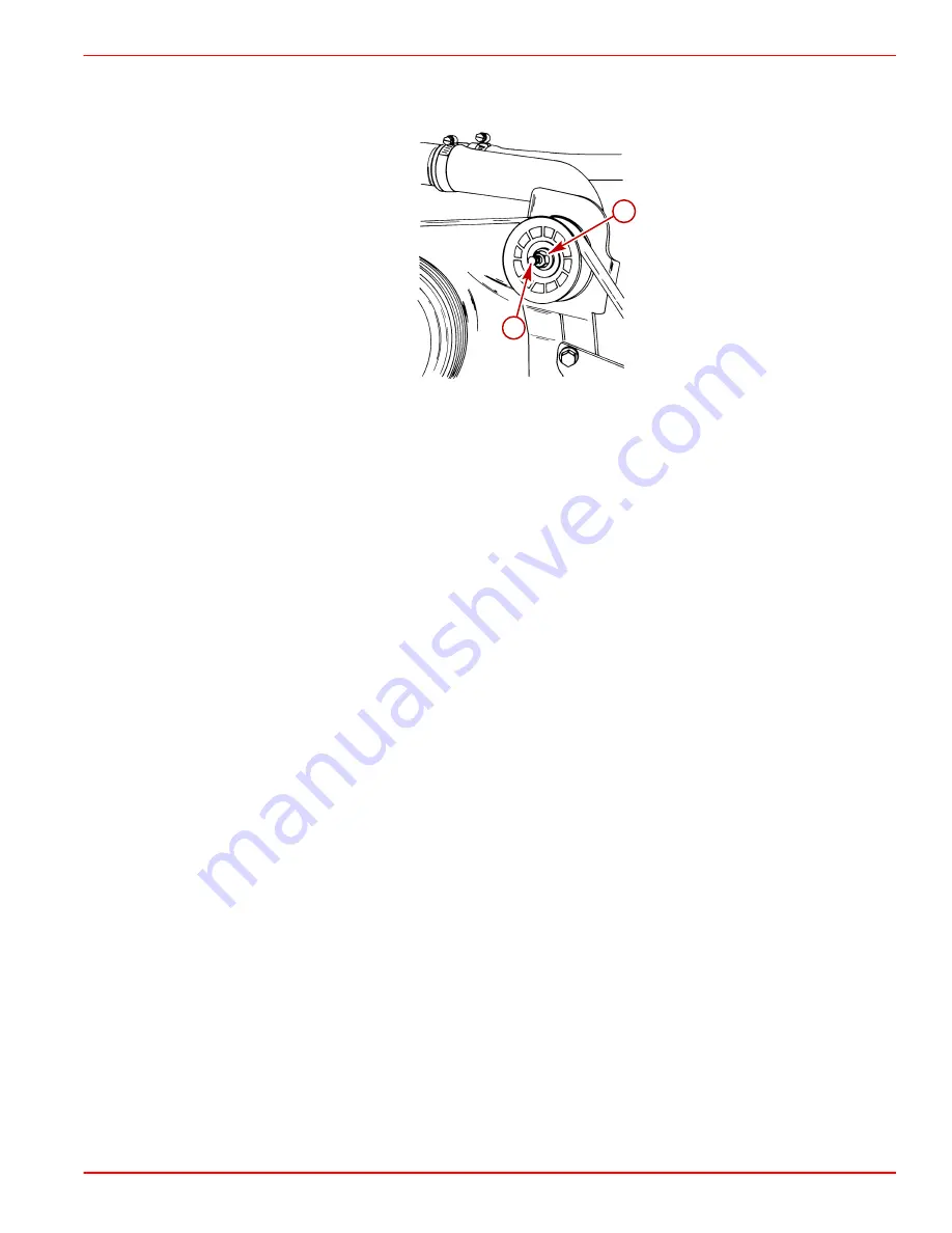
7. While holding adjustment stud at the correct belt tension, tighten 5/8 in. locking nut.

8. Run engine for a short period of time and recheck belt adjustment.

74908

a

b

a -

5/8 in. Locking Nut

b -

5/16 in. Adjusting Stud

Ignition Timing

Thunderbolt V Models

1. Connect timing light to number 1 spark plug wire.

2. Connect a shop tachometer to the engine.

IMPORTANT: Before starting the engine, connect a jumper wire from the ignition tim-
ing lead to a good ground. This has to be done before the ignition key is turned ON
to lock the ignition module into Base Timing Mode.

3. Before starting the engine, connect jumper wire from timing lead to a good ground.

NOTE: The PUR/WHT timing lead is located towards the front of the engine near the fuel
line or near the distributor, as equipped for your model.

4. Start engine and run at 1300 rpm until it reaches normal operating temperature.

5. Disconnect throttle cable from the carburetor.

6. With engine at idle rpm, adjust the carburetor idle rpm screw to the specified engine idle

rpm.

7. With the engine still at idle rpm, check the ignition timing. If incorrect, rotate the

distributor until timing is correct. Torque clamping screw to 18 lb-ft (25 Nm).

8. Adjust the idle mixture screw. Inward is LEAN, outward is RICH.

9. Recheck ignition timing.

10. Stop engine. Remove timing light, jumper wire and shop tachometer.

IMPORTANT: Timing jumper wire has to be removed or the ignition module will stay
locked in the Base Timing Mode and it will not be able to advance the ignition timing
correctly when the engine rpm is increased.

11. Adjust and reinstall throttle cable. Open and close remote control throttle lever. Ensure

that the carburetor throttle lever is contacting the idle rpm adjusting screw every time.

12. Restart the engine, increase rpm to 1300 then return to idle position slowly and shut the

engine off. Ensure that the carburetor throttle lever is contacting the idle rpm screw.

13. Shut engine off.

Summary of Contents for MerCruiser MCM 4.3L BRAVO

Page 1: ...1B 11 Checking Engine Oil Level Filling 1B 12 Changing Oil and Filter 1B 12 Changing Water Separating Fuel Filter 1B 13 Power Steering System 1B 15 Checking Fluid Level 1B 15 Engine Cold 1B 15 Filling...

Page 2: ...g Light 91 99379 Quicksilver Scan Tool 91 823686A2 Lubricants Sealants Adhesives Description Part Number Quicksilver Liquid Neoprene 92 25711 3 Quicksilver 2 4 C Marine Lubricant With Teflon 92 825407...

Page 3: ...ents CAUTION Always disconnect battery cables from battery BEFORE working around electrical systems components to prevent injury to yourself and damage to electrical system should a wire be accidental...

Page 4: ...or loose or damaged connec tions Test MerCathode unit output on Bravo Models Retorque engine mounts Check spark plugs wires distributor cap and ignition timing Check and adjust idle speed Clean flame...

Page 5: ...1 1 mm Timing at idle rpm 4 10 BTDC 8 BTDC Preliminary Idle Mixture 1 1 4 Turns DNA Thermostat 160 F 71 C 1 Power Rated in Accordance with NMMA National Marine Manufacturers Association rating proced...

Page 6: ...5 14 1 Closed Cooling System 20 19 1 Always use dipstick to determine exact quantity of oil or fluid required 2 Seawater Cooling System capacity information is for winterization use only Sterndrives N...

Page 7: ...full throttle acceleration from IDLE speed Do not operate at full throttle until engine reaches normal operating temperature After Break in Period To help extend the life of your Mercury MerCruiser po...

Page 8: ...ne is required in certain areas of the USA The two types of oxygenates used in these fuels are Alcohol Ethanol or Ether MTBE or ETBE If Ethanol is the oxygen ate that is used in the gasoline in your a...

Page 9: ...D Fuel leakage from any part of fuel system can be a fire and explosion hazard which can cause serious bodily injury or death Careful periodic inspection of entire fuel system is mandatory particularl...

Page 10: ...l becomes cloudy use the middle of the cloudy band Power Steering Fluid Use Quicksilver Power Trim and Steering Fluid or automatic transmission Fluid ATF Dexron III Coolant for Closed Cooling System C...

Page 11: ...rankcase oil selection The oil filter should always be changed with oil 70534 Quicksilver 4 Cycle Marine Engine Oil SAE 20W SAE 30W SAE 40W 32 F 0 C 50 F 10 C AIR TEMPERATURE Overfilled Crankcase Oil...

Page 12: ...bring level up to but not over the FULL mark on dipstick Changing Oil and Filter 1 Start engine and run until it reaches normal operating temperatures IMPORTANT Change oil when engine is warm from ope...

Page 13: ...UTION The electric fuel pump and factory installed water separating fuel filter have been carefully designed to function properly together Do not install additional fuel filters and or water separatin...

Page 14: ...a a Fuel Filter b Sealing Ring 3 Coat sealing ring on new filter with motor oil 4 Thread filter onto bracket and tighten securely by hand Do not use a filter wrench 5 Start and run engine 6 Check fil...

Page 15: ...p opening to bring level up to FULL HOT mark on dipstick DO NOT OVERFILL 5 If fluid is not visible in reservoir a leak exists in the power steering system Find cause and correct Engine Cold 1 With eng...

Page 16: ...wheel back and forth to end of travel in each direction several times 5 Recheck fluid level and add fluid if necessary 6 Install vented fill cap Tighten securely CAUTION DO NOT operate engine without...

Page 17: ...er engine has cooled turn cap 1 4 turn to allow any pressure to escape slowly then push down and turn cap all the way off 1 Coolant level in heat exchanger should be full to bottom of filler neck IMPO...

Page 18: ...ropeller is clear and no one is standing nearby To avoid possible injury remove propeller CAUTION Do not run engine above 1500 rpm when flushing Suction created by seawater pick up pump may collapse f...

Page 19: ...Do not run engine above 1500 rpm when flushing Suction created by seawater pick up pump may collapse flushing hose causing engine to overheat CAUTION Watch temperature gauge on dash to ensure that en...

Page 20: ...guide contact surfaces with SAE 30W motor oil 74941 b a a a a b 71359 2 Barrel Carbureted Models EFI Models a Pivot Points b Guide Contact Surface Shift Cable MCM STERNDRIVE MODELS 1 Lubricate pivot p...

Page 21: ...val and installation if necessary IMPORTANT Sterndrive Unit does not have to be removed to grease coupler 1 Lubricate engine coupler splines through grease fitting on coupler by applying approxi matel...

Page 22: ...extremely flammable and highly explosive under certain conditions Be careful when cleaning flame arrestor and crankcase ventilation hoses Be sure that ignition is OFF DO NOT smoke or allow sources of...

Page 23: ...ation hose in solvent Blow dry with compressed air 6 Inspect crankcase ventilation hose for cracks or deterioration and replace if necessary 7 Reinstall flame arrestor and crankcase ventilation hose 8...

Page 24: ...999 Serpentine Belt Routing S N 0L619083 and Below Alpha With Power Steering Bravo With Power Steering Alpha With Closed Cooling Bravo Without Power Steering Without Power Steering Alpha With Closed C...

Page 25: ...R 25 90 861328 1 NOVEMBER 1999 Page 1B 25 Serpentine Belt Routing Continued S N 0L619084 and Above 76502 76503 Alpha With Power Steering Bravo With Power Steering 76445 76463 Alpha Without Power Steer...

Page 26: ...on REMOVAL 1 Loosen 5 8 in locking nut on adjustment stud 2 Turn adjustment stud and loosen belt 3 Remove drive belt INSTALLATION AND ADJUSTMENT 4 Install drive belt on pulleys 5 Adjust tension by loo...

Page 27: ...til it reaches normal operating temperature 5 Disconnect throttle cable from the carburetor 6 With engine at idle rpm adjust the carburetor idle rpm screw to the specified engine idle rpm 7 With the e...

Page 28: ...ine rpm NOTE MEFI 3 models only ECM will automatically adjust engine rpm to approximately 1200 rpm when put in the service mode on a scan tool or when using the timing tool 5 Check ignition timing If...

Page 29: ...ting fuel filter when removing it to help avoid fuel spray ing on the engine CAUTION If boat is in the water seacock water inlet valve if equipped must be closed until engine is to be restarted to pre...

Page 30: ...NOT run engine above 1500 rpm as suction created by seawater pickup pump may collapse water supply hose and cause engine to overheat WARNING Be sure that engine compartment is well ventilated and tha...

Page 31: ...ot available Fuel tanks should be drained as low as possible and Quicksilver Gasoline Stabilizer for Marine Engines added to any fuel remaining in the tank Refer to Fuel Requirements for additional in...

Page 32: ...res c Squirt the remaining 2 ounces 57 g of Storage Seal or oil rapidly into carburetor just as the engine begins to stall due to lack of fuel Allow engine to stop 10 Turn ignition key to OFF position...

Page 33: ...ttings 2 Remove drain plugs port and starboard from cylinder block or cylinder block Y fitting CAUTION Avoid product damage Do not disturb the Y fitting when removing the drain plug There is an igniti...

Page 34: ...ting pump hose or drain plug as equipped 72587 a 76038 b a Hose Water Circulating Pump To Thermostat Housing b Water Circulating Pump Hose Drain Plug 5 Remove the drain plug from the water tube or Coo...

Page 35: ...the propylene glycol antifreeze contains a rust inhibitor and is recommended for use in marine engines Be certain to follow the propylene glycol manufacturer s recommendations 9 For additional assuran...

Page 36: ...IMPORTANT Engine must be as level as possible to ensure complete draining of cooling system 1 Remove drain plug from bottom of port and starboard exhaust manifolds 74073 a a Drain Plug 2 Remove the dr...

Page 37: ...xchanger 5 Repeatedly clean out drain holes using a stiff piece of wire Do this until entire system is drained 6 After seawater section of cooling system has been drained completely a Install all drai...

Page 38: ...dometer Pitot Tube b Anode Cavity Vent Hole c Anode Cavity Drain Passage d Gear Housing Water Drain Hole One Each Port and Starboard e Gear Housing Cavity Vent Hole f Gear Housing Cavity Drain Hole 2...

Page 39: ...drive Service Manual CAUTION When installing battery in next step be sure to connect positive battery cable to positive terminal and negative grounded battery cable to negative battery terminal If bat...

Page 40: ...MAINTENANCE SERVICE MANUAL NUMBER 25 Page 1B 40 90 861328 1 NOVEMBER 1999 THIS PAGE IS INTENTIONALLY BLANK...

Reviews: