background image

Section 4 - Maintenance 

Page  32

90-8M0133679   

eng

  JUNE 2017

Owner and Operator Responsibilities

It is the operator's responsibility to perform all safety checks, to ensure that all lubrication and maintenance instructions are

complied with for safe operation, and to return the unit to a Mercury Diesel authorized repair facility for a periodic checkup.
Normal maintenance service and replacement parts are the responsibility of the owner or operator and, as such, are not

considered defects in workmanship or material within the terms of the warranty. Individual operating habits and usage

contribute to the need for maintenance service.
Proper maintenance and care of your power package will ensure optimum performance and dependability and will keep your

overall operating expenses at a minimum. See your Mercury Diesel authorized repair facility for service aids.

Dealer Responsibilities

It is the dealer's responsibility to provide predelivery inspection and preparation:

Before delivery, making certain that the Mercury power package is in proper operating condition.

Making all necessary adjustments for maximum efficiency.

Explaining and demonstrating the operation of the power package and the boat.

Providing a copy of the Predelivery Inspection Checklist.

Completing the warranty registration and immediately submitting it to Mercury Marine via MercNET, e‑mail, or mail. All

power packages must be registered for warranty purposes.

Cleaning Care Recommendation

Do Not Use Caustic Cleaning Chemicals

IMPORTANT: Do not use caustic cleaning chemicals on any part of the MerCruiser power package. Some cleaning products

contain strong caustic agents. For example, some hull cleaners contain hydrochloric acid. These cleaners can degrade some of

the components they contact, including critical steering fasteners.
Damage to steering fasteners may not be obvious during visual inspection, and this damage may lead to catastrophic failure.

Some caustic cleaning chemicals may cause or accelerate corrosion. Exercise caution when using cleaning chemicals around

the power package, and follow the recommendations on the packaging of the cleaning product.

Cleaning Gauges

IMPORTANT: Never use high‑pressure water to clean gauges.
Routine cleaning of the gauges is recommended to prevent a buildup of salt and other environmental debris. Crystalized salt

can scratch the gauge display lens when using a dry or damp cloth. Ensure that the cloth has a sufficient amount of fresh water

to dissolve and remove salt or mineral deposits. Do not apply aggressive pressure on the display lens while cleaning.
When water marks cannot be removed with a damp cloth, mix a 50/50 solution of warm water and isopropyl alcohol to clean the

display lens. 

Do not use

 acetone, mineral spirits, turpentine type solvents, or ammonia based cleaning products. The use of

strong solvents or detergents may damage the coating, the plastics, or the rubber keys on the gauges. If the gauge has a sun

cover available, it is recommended that the cover be installed when the unit is not in use to prevent UV damage to the plastic

bezels and rubber keys.

Cleaning Remote Controls

IMPORTANT: Never use high‑pressure water to clean remote controls.
Routine cleaning of the remote control external surfaces is recommended to prevent a buildup of salt and other environmental

debris. Use a cloth towel which has a sufficient amount of fresh water to dissolve and remove salt or mineral deposits.
When water marks cannot be removed with a damp cloth, mix a 50/50 solution of warm water and isopropyl alcohol to clean the

remote control. 

Do not use

 acetone, mineral spirits, turpentine type solvents, or ammonia based cleaning products. The use of

strong solvents or detergents may damage the coating, the plastics, or the rubber components on the remote control.

Maintenance

!

 WARNING

Performing  service  or  maintenance  without  first  disconnecting  the  battery  can  cause  product  damage,  personal  injury,  or

death due to fire, explosion, electrical shock, or unexpected engine starting. Always disconnect the battery cables from the

battery before maintaining, servicing, installing, or removing engine or drive components.

!

 WARNING

Fuel vapors trapped in the engine compartment may be an irritant, cause difficulty breathing, or may ignite resulting in a fire

or explosion. Always ventilate the engine compartment before servicing the power package.

Summary of Contents for MerCruiser Diesel Inboard 2.8L

Page 1: ...2 8L and 4 2L Diesel Inboard Models OPERATION MAINTENANCE MANUAL ...

Page 2: ......

Page 3: ...ith these special instructions while performing the service plus common sense operation are major accident prevention measures WARNING Indicates a hazardous situation which if not avoided could result in death or serious injury CAUTION Indicates a hazardous situation which if not avoided could result in minor or moderate injury NOTICE Indicates a situation which if not avoided could result in engi...

Page 4: ...s the applicable limited warranty coverage whether the engine participated in one of the test programs described above or not Copyright and Trademark Information MERCURY MARINE All rights reserved Reproduction in whole or in part without permission is prohibited Alpha Axius Bravo One Bravo Two Bravo Three Circle M with Waves Logo K planes Mariner MerCathode MerCruiser Mercury Mercury with Waves Lo...

Page 5: ...ature and Cold Weather Operation 17 Drain Plug and Bilge Pump 18 Trailering the Boat 18 Starting Shifting and Stopping 18 Before Starting the Engine 18 Important Information SmartStart 18 Starting a Cold Engine 18 Engine Warm Up 19 Starting a Warm Engine 19 Shifting 19 Trolling Valve Operation on Technodrive Transmissions 19 Engine Shut Down Stopping 20 Protecting People in the Water 20 While Boat...

Page 6: ...7 With the Boat out of the Water 57 With the Boat in the Water 58 Engine Seawater Pump Inspection 59 Replacing the Engine Coolant in the Closed Cooling System 60 Draining the Closed Cooling System 60 Filling the Closed Cooling System 61 Corrosion Protection 62 General Information 62 Engine Corrosion Protection Components 62 Removal 62 Cleaning and Inspection 63 Installation 63 Antifouling Paint 64...

Page 7: ...r Submersion 78 Replacement Service Parts 78 Parts and Accessories Inquiries 78 Resolving a Problem 78 Contact Information for Mercury Marine Customer Service 79 Customer Service Literature 79 English Language 79 Other Languages 80 Ordering Literature 80 United States and Canada 80 Outside the United States and Canada 80 Section 8 Maintenance Log Scheduled Maintenance Log 82 Vessel Maintenance Not...

Page 8: ...Page iv 90 8M0133679 eng JUNE 2017 ...

Page 9: ...stem 3 Switches 4 Lanyard Stop Switch 4 Keep the Lanyard Stop Switch and Lanyard Cord in Good Operating Condition 5 Instrumentation 6 VesselView 6 SmartCraft Digital Instruments 6 System Link Digital Instruments 7 Emergency Stop Switch 7 Remote Controls 8 Panel Mount Features 8 Console Mount Features 8 Overload Protection Upper Engine Circuit Breaker Panel 9 Overload Protection Port Side Power Dis...

Page 10: ...tion or performance of the engine and neither boatbuilders nor dealers may remove the engine data label or the engine component it is affixed to before sale If modifications are necessary or the engine data label is damaged contact Mercury Marine about the availability of a replacement The owner or operator is not to modify the engine in any manner that would alter the horsepower or allow exhaust ...

Page 11: ...monitors critical components and informs the operator when a malfunction has occurred The warning system is not capable of protecting the power package from damage caused by a malfunction When an electronic control system detects a recordable malfunction the audio warning system will sound to alert the operator The duration and type of horn sound depend upon the nature of the fault condition In th...

Page 12: ...C position ON In the ON position all electrical circuits and instrumentation receive power The engine can be started with an optional start stop switch START Turn the key to the start position and release to start the engine NOTE The key can only be removed with the key switch in the OFF position Dual Engine Start Stop Switch 28082 A start stop switch is optional equipment The start stop switch wo...

Page 13: ...ately but the boat will continue to coast for some distance depending upon its velocity While the boat is coasting it can cause injury to anyone in the boat s path as it would under power Instruct all passengers on the proper starting and operating procedures should they be required to operate the boat in an emergency WARNING If the operator falls out of the boat stop the engine immediately to red...

Page 14: ... the operator to monitor and control a wide range of vessel systems from a single display Refer to the VesselView operator s manual for more information 61325 VesselView SmartCraft Digital Instruments The SmartCraft instrument package augments the VesselView display The instrument package may include Tachometer Speedometer Engine coolant temperature Engine oil pressure Battery voltage Fuel consump...

Page 15: ...iately but the boat can continue to coast for some distance depending upon the velocity and degree of any turn at shutdown While the boat is coasting it can cause injury to anyone in the boat s path as seriously as the boat would when under power We recommend instructing other occupants on proper starting and operating procedures should they need to operate the engine in an emergency Accidental or...

Page 16: ...n and should only be used to assist in starting the engine Lanyard stop switch Turns the ignition off whenever the operator when attached to the lanyard moves far enough away from the operator s position to activate the switch See Lanyard Stop Switch for information on the use of this switch Control handle The shift and throttle are controlled by the movement of the control handle Push the control...

Page 17: ...tch See the Power Trim section for detailed power trim operating procedures Trailer switch Used to raise the sterndrive for trailering launching beaching or shallow water operation See Power Trim for detailed trailer switch operation Overload Protection Upper Engine Circuit Breaker Panel If an electrical overload occurs a fuse will open blow or a circuit breaker will open trip Find and correct the...

Page 18: ...replacing the fuse or resetting the circuit breaker NOTE In an emergency when the engine must be operated and the cause for the high current draw cannot be located and corrected turn off or disconnect all the accessories connected to the engine and instrumentation wiring The circuit breaker should automatically reset If the breaker remains open the electrical overload has not been eliminated Furth...

Page 19: ... never have to be concerned about whether or not you are protected The system will respond to a problem by sounding the warning horn for six seconds and or reducing engine power in order to provide engine protection If Engine Guardian has been activated reduce the engine speed The problem will need to be identified and corrected The system must be reset before the engine will operate at higher spe...

Page 20: ...Section 1 Getting to Know Your Power Package Notes Page 12 90 8M0133679 eng JUNE 2017 ...

Page 21: ...d Engine 18 Engine Warm Up 19 Starting a Warm Engine 19 Shifting 19 Trolling Valve Operation on Technodrive Transmissions 19 Engine Shut Down Stopping 20 Protecting People in the Water 20 While Boat is in Operation 20 While the Boat is Stationary 20 High Speed and High Performance 20 Passenger Safety In Pontoon Boats and Deck Boats 20 Boats Having An Open Front Deck 20 Boats With Front Mounted Rai...

Page 22: ...passengers are boarding unloading or are near the back stern of the boat Shifting the drive unit into neutral is not sufficient Use personal flotation devices Federal law requires that there be a U S Coast Guard approved life jacket personal flotation device correctly sized and readily accessible for every person onboard plus a throwable cushion or ring We strongly advise that everyone wear a life...

Page 23: ...w enforcement Carbon Monoxide Exposure Be Alert To Carbon Monoxide Poisoning Carbon monoxide CO is a deadly gas that is present in the exhaust fumes of all internal combustion engines including the engines that propel boats and the generators that power boat accessories By itself CO is odorless colorless and tasteless but if you can smell or taste engine exhaust you are inhaling CO Early symptoms ...

Page 24: ...ion Information Launching IMPORTANT Install the bilge drain plug before launching the boat Duty Cycle Rating Requirements IMPORTANT Damage caused by incorrect application or failure to operate the power package within the specified operating parameters will not be covered by the Mercury Marine Limited Warranty Mercury Diesel engines must be used in applications that meet the operation specificatio...

Page 25: ...ited Warranty NOTICE Water trapped in the seawater section of the cooling system can cause corrosion or freeze damage Drain the seawater section of the cooling system immediately after operation or before any length of storage in freezing temperatures If the boat is in the water keep the seacock closed until restarting the engine to prevent water from flowing back into the cooling system If the bo...

Page 26: ...of oil for the prevailing temperature Refer to Section 3 Specifications Ensure that all electrical connections are secure Check all applicable items in the Maintenance Schedules and Operation Chart Perform any other necessary checks as indicated by your Mercury Diesel authorized repair facility or specified in your boat owner s and operation manual Important Information SmartStart IMPORTANT This p...

Page 27: ...s fuel filter or fuel lines c Check the engine and the transmission oil filter oil lines oil line connectors and oil pan for leaks d Check the coolant hoses heat exchanger connections aftercooler water pump and drain fittings for leaks 4 Locate and correct any problems or see your Mercury Diesel authorized repair facility if you are unable to determine the problem Starting a Warm Engine 1 Turn on ...

Page 28: ...the water on the propeller to cause the propeller to rotate This neutral propeller rotation can cause serious injury While the Boat is Stationary WARNING A spinning propeller a moving boat or any solid device attached to the boat can cause serious injury or death to swimmers Stop the engine immediately whenever anyone in the water is near your boat Shift into neutral and shut down the engine befor...

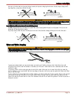
Page 29: ...jumping can cause serious injury or death from occupants being thrown within or out of the boat Avoid wave or wake jumping whenever possible mc79680 1 Operating recreational boats over waves and wakes is a natural part of boating However when this activity is done with enough speed to force the boat hull partially or completely out of the water certain hazards arise particularly when the boat reen...

Page 30: ...ter striking a submerged object stop the engine as soon as possible and inspect the drive system for any broken or loose parts If damage is present or suspected take the power package to an authorized dealer for a thorough inspection and necessary repair The boat should also be checked for any hull fractures transom fractures and water leaks Operating with damaged underwater drive components rudde...

Page 31: ...llow the engine power package to operate at the rated engine RPM with a maximum load If full throttle operation is below the engine rated RPM the propeller must be changed to prevent loss of performance and possible engine damage On the other hand operating an engine above the rated engine RPM will cause higher than normal wear or damage After initial propeller selection the following common probl...

Page 32: ...engine reaches normal operating temperature Check the engine oil level frequently Add oil as needed High oil consumption is normal during the break in period After the 20 Hour Break In Period To help extend the life of your power package Mercury Marine recommends the following Change the engine oil and filter and the transmission fluid at the interval indicated in the Maintenance Schedule Refer to...

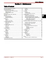
Page 33: ...ecifications Table of Contents Fuel Requirements 26 Diesel Fuel in Cold Weather 26 Antifreeze Coolant 26 Engine Oil 27 Engine Specifications 28 2 8L Specification 28 4 2L Specification 28 Fluid Specifications 28 Engine 28 2 8L 29 4 2L 29 Transmission 29 Approved Paints 29 3 ...

Page 34: ...OTE If your engine suddenly becomes noisy after a fill up you possibly received substandard fuel with a low cetane rating On engines that use high sulphur content diesel fuel this will greatly increase Corrosion on metal parts Deterioration of elastomer and plastic parts Excessive wear of internal engine parts particularly bearings and corrosion and extensive damage to other engine parts Difficult...

Page 35: ...ut knowing that they are compatible Refer to the coolant manufacturer s instructions The acceptable antifreeze coolants is listed in the following table Refer to Section 4 Maintenance for respective change intervals Tube Ref No Description Where Used Part No 122 Extended Life Antifreeze Coolant Closed cooling system 92 877770K1 Engine Oil NOTICE Discharge of oil coolant or other engine drive fluid...

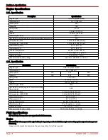
Page 36: ...ion Description Specifications Engine type In line 6 cylinder diesel Displacement 4 2 L 254 cid Horsepower 270 320 350 Kilowatt 199 235 257 Firing order 1 5 3 6 2 4 Bore 94 mm 3 700 in Stroke 100 mm 3 937 in Rated engine RPM 3800 Idle RPM in neutral engine at normal operating temperature 600 Oil pressure at idle 2 1 bar 210 kPa 30 psi Oil pressure at 3800 RPM 6 6 bar 660 kPa 93 psi Thermostat wate...

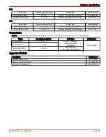
Page 37: ...ine Oil 92 858042K01 Closed cooling system 17 25 18 2 Mercury Extended Life Antifreeze 92 877770K1 Transmission NOTE Capacities are for the transmission only and do not include the fluid cooler or fluid cooler hose capacities Model Capacity liters US qt Fluid Type Part Number ZF Marine 63A 4 4 2 Dexron III Automatic Transmission Fluid or Equivalent Obtain Locally ZF Marine 63IV 4 4 4 6 Technodrive...

Page 38: ...Section 3 Specifications Notes Page 30 90 8M0133679 eng JUNE 2017 ...

Page 39: ...6 4 2 Air Filter 46 Removal 46 Inspection 47 Installation 48 Water Separating Fuel Filter 48 Draining 49 Replacing 49 Filling 51 Fuel System 52 Priming 52 Filling Bleeding 52 Fuel Tank Cleaning and Flushing 53 Seawater System 53 Draining the Seawater System 53 Checking the Seawater Pickups 55 Cleaning the Seawater Strainer if Equipped 55 Flushing the Seawater System Inboard Models 57 With the Boat...

Page 40: ... recommendations on the packaging of the cleaning product Cleaning Gauges IMPORTANT Never use high pressure water to clean gauges Routine cleaning of the gauges is recommended to prevent a buildup of salt and other environmental debris Crystalized salt can scratch the gauge display lens when using a dry or damp cloth Ensure that the cloth has a sufficient amount of fresh water to dissolve and remo...

Page 41: ...l tools and equipment are required to perform certain repairs Failure to use the correct special tools and equipment can result in severe damage to the product Always have a Mercury Diesel authorized repair facility service your power package and do periodic maintenance inspections to help provide safe and trouble free boating Inspection Inspect your power package often and at regular intervals to...

Page 42: ... water or polluted water flush the seawater section of the cooling system after each use Drain any water from the primary fuel filter after each use Drain any water from both fuel filters if operating in freezing temperatures Weekly Drain any water from the fuel filters Check the seawater inlets for debris or marine growth Check and clean the seawater strainer Every two months Check the battery co...

Page 43: ... seawater strainer Check the closed cooling fluid level and level of protection Check the run history for faults Check the engine timing belt Every 2 years Replace the engine coolant Every 1000 hours or 5 years whichever occurs first Replace the engine timing belt Clean the fuel tank Clean the aftercooler core According to OEM Schedule Check the engine to propeller shaft alignment Engine Oil NOTIC...

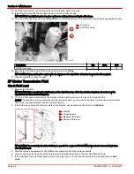
Page 44: ...Oil 4 2L Capacity Fluid Type Engine oil with filter 13 8 L 14 6 U S qt 4 Cycle 15W 40 Marine Engine Oil IMPORTANT Always use the dipstick to determine the amount of oil required to refill the engine oil 3 Install the oil fill cap Changing Oil and Filter See the Maintenance Schedule for the change interval You should change the engine oil before placing the boat in storage IMPORTANT Change the engi...

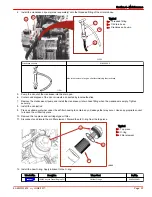
Page 45: ...e oil pump and install the crankcase oil drain hose fitting when the crankcase is empty Tighten securely 8 Install the oil dipstick 9 Place a suitable container under the oil filter housing to contain any oil leakage that may occur Use an appropriate socket to loosen the oil filter top piece 10 Remove the top piece and cartridge type oil filter 11 Disconnect and discard the old filter element Disc...

Page 46: ...level rest the dipstick on top of the threaded housing hole Do not screw the dipstick into the threaded housing hole 2 Check the fluid level as indicated on the dipstick with the dipstick resting on the top of the threaded hole NOTE The fluid level may be somewhat over the maximum mark as some of the fluid from the transmission fluid cooler and hoses may have drained back into the transmission 3 I...

Page 47: ...oil or fluid required NOTE Capacities are for the transmission only and do not include the fluid cooler or fluid cooler hose capacities Model Capacity Fluid type Part Number ZF Marine 63A 4 0 L 4 2 US qt Dexron III Automatic Transmission Fluid or Equivalent Obtain locally ZF Marine 63IV 4 4 L 4 6 US qt 2 Install the dipstick 3 Check the fluid level Refer to Check Fluid Level Change Fluid 1 Clean t...

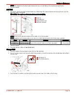
Page 48: ...ing installation 8 Install the fluid filter assembly in the transmission cavity by turning clockwise and pushing at the same time 9 Using a 6 mm Allen wrench turn the filter assembly nut clockwise to tighten Tighten the nut to the specified torque a Assembly nut b Fluid filter assembly Description Nm lb in lb ft Filter assembly nut 7 62 10 Fill the transmission to the proper level with the specifi...

Page 49: ...check the fluid level with the dipstick resting on the top of the threaded hole 6 If the fluid level is low add transmission fluid to bring the level up to the maximum mark on the dipstick See Add Fluid NOTE If the transmission fluid level was extremely low see your local Mercury Diesel authorized repair facility 7 Install the dipstick Add Fluid 1 If necessary add specified transmission fluid thro...

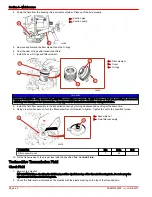
Page 50: ...s as required 1 Remove the fill cap and dipstick 2 Remove the transmission fluid drain plug and drain the transmission into a suitable container a Fill cap and dipstick b Drain plug 3 Dispose of the waste according to local regulations 4 Reinstall the transmission fluid drain plug 5 Tighten the drain plug to the specified torque Description Nm lb in lb ft Transmission fluid drain plug 17 150 6 Cle...

Page 51: ...o 80 SAE Engine Oil 30W Transmission filter element O ring Obtain Locally 11 Reinstall the filter element a Filter element b O ring NOTICE Improper installation of the transmission fluid filter assembly may cause the fluid to foam or leak out resulting in decreased efficiency and damage to the transmission Properly seat the transmission fluid filter during installation 12 Replace the securing tab ...

Page 52: ...ible check the engine coolant before starting the engine 1 Allow the engine to cool 2 Remove the pressure cap from the coolant expansion tank 3 The coolant level in the coolant expansion tank should be above the coolant level indicator attached to the bottom of the coolant cap a Filler neck b Coolant cap c Level indicator 4 If the coolant level is low a Inspect the coolant recovery system for leak...

Page 53: ...the upper and lower marks if applicable a Pressure cap b Bottom of fill neck Description Where Used Part Number Mercury Extended Life Antifreeze Closed cooling system 877770K1 IMPORTANT When installing the pressure cap be sure to tighten it securely to prevent coolant loss 4 Install the pressure cap Tighten securely Changing Change replace the engine coolant at the prescribed interval See Replacin...

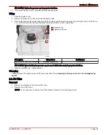
Page 54: ...place the air filter at the recommended interval See Maintenance Schedules for the replacement interval under normal conditions Installation IMPORTANT Treatment such as partial oil saturation is not required and is not recommended on the foam element before use The foam element must be clean and dry for proper filtration 1 Install the air filter cartridge onto the air filter bracket 2 Install the ...

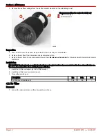
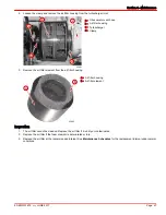
Page 55: ...the air filter element from the air filter housing a Air filter housing b Air filter element Inspection 1 The air filter cannot be cleaned Replace the air filter if it is dirty or contaminated 2 Replace the air filter if the foam element is deteriorated or torn 3 Replace the air filter at the recommended interval See Maintenance Schedules for the replacement interval under normal conditions a b c ...

Page 56: ...NG Fuel is flammable and explosive Ensure that the key switch is off and the lanyard is positioned so that the engine cannot start Do not smoke or allow sources of spark or open flame in the area while servicing Keep the work area well ventilated and avoid prolonged exposure to vapors Always check for leaks before attempting to start the engine and wipe up any spilled fuel immediately NOTICE Water...

Page 57: ...ns In cold weather where there is a possibility that the condensed water will freeze drain the filter shortly after the end of daily operations NOTE Place a suitable container under the fuel filter to catch contaminated fuel or water Dispose of properly 1 Place a container under the drain cap on the filter 2 Open the drain by turning the drain cap counterclockwise as viewed from the bottom of the ...

Page 58: ... drain cap and use it on the new filter Be sure to replace the O ring on the drain cap 4 Remove the drain cap and O ring seal from the bottom of the existing fuel filter Note the position of the O ring seal Typical a Drain cap b O ring seal 5 Discard the used filter and O ring seal as defined by local authorities 6 Install the O ring and drain cap on the new water separating fuel filter Typical a ...

Page 59: ...uel leaks 13 Connect the battery cables 14 Start and operate the engine Check the filter connection for fuel leaks If leaks exist recheck the filter installation If leaks continue stop the engine immediately and contact your Mercury Diesel authorized repair facility Filling A type of hand pump and primer plunger is located on the fuel filter bracket and is used to Refill the fuel filter when drain...

Page 60: ...Fuel System Priming Prime the engine if it has not been run for an extended period or if the engine will not start 1 Move the hand pump and primer plunger up and down several times as previously outlined 2 Attempt to start the engine Filling Bleeding NOTE Follow this procedure if the fuel system was run dry or if part of the fuel system was drained for a service function 1 See Water Separating Fue...

Page 61: ...e and ensure the bilge pump is operational before draining Do not operate the engine with the drain system open IMPORTANT The engine must be as level as possible to ensure complete draining of the cooling system IMPORTANT The boat must not be operating during this procedure Drain the power package s seawater system before cold weather freezing temperature seasonal storage or extended storage 1 Rem...

Page 62: ...e seawater inlet hose from the connector on the seawater pump hose and drain 2 8 4 2 a Seawater inlet hose b Connector c Seawater pump hose 7 Repeatedly clean out the drain holes using a stiff piece of wire until the seawater section is completely drained 8 On models equipped with a seawater strainer a Remove the drain plug and washer if equipped b Remove both hoses from the seawater strainer and ...

Page 63: ... pickup are clean and not obstructed 54902 Typical through the hull seawater pickup Cleaning the Seawater Strainer if Equipped NOTICE An open seawater strainer or seacock during some service or maintenance procedures can introduce water into the boat causing damage or sinking the boat Always close the water supply from the seawater pump water inlet or seacock when performing service or maintenance...

Page 64: ...oth the strainer and housing with clean water e Inspect the cover gasket and replace if damaged a Strainer cover b Strainer basket c Seal CAUTION Seawater leaking from the seawater strainer could cause excess water in the bilge damaging the engine or causing the boat to sink Do not overtighten the cover screws or the cover may warp and introduce seawater into the bilge 4 For metal seawater straine...

Page 65: ...perating in saltwater brackish water polluted water or water with a high mineral content to avoid salt or silt buildup For best results we recommend flushing the seawater system after each outing After each operation in saltwater and before storage the seawater cooling system must be flushed With the Boat out of the Water NOTICE Without sufficient cooling water the engine the water pump and other ...

Page 66: ...not operate the engine above 1400 RPM out of the water and without sufficient cooling water supply 6 Operate the engine at idle speed in neutral for about 10 minutes or until the discharge water is clear 7 Observe the water temperature gauge to ensure that the engine is operating in the normal range 8 Stop the engine 9 Shut off the water tap 10 Remove the adapter from the seawater pump inlet hose ...

Page 67: ...ithout sufficient cooling water supply 5 Operate the engine at idle speed in neutral for about 10 minutes or until the discharge water is clear 6 Observe the water temperature gauge to ensure that the engine is operating in the normal range 7 Stop the engine 8 Shut off the water tap 9 Remove the adapter from the seawater pump inlet hose connection 10 To prevent water from siphoning into the boat o...

Page 68: ...tion must be filled year round with the required coolant If the engine will be exposed to freezing temperatures ensure that the closed cooling section is filled with a solution of ethylene glycol antifreeze and water properly mixed to protect the engine to the lowest temperature to which it will be exposed Do not use propylene glycol antifreeze in the closed cooling section of the engine CAUTION A...

Page 69: ...ing replaced or the level is low slowly add the specified coolant to the level indicated in the table Coolant level in expansion tank All models Within 25 mm 1 in of the bottom of the filler neck or between the upper and lower marks if marked Description Where Used Part Number Mercury Extended Life Antifreeze Closed cooling system 877770K1 NOTICE Without sufficient cooling water the engine the wat...

Page 70: ...ll eventually cause the need for replacement of power package components exposed to water To help control the effects of galvanic corrosion Mercury power packages come with several sacrificial anodes and other corrosion protection devices For a more comprehensive explanation of corrosion and corrosion protection refer to the Marine Corrosion Protection Guide IMPORTANT Replace sacrificial anodes if...

Page 71: ...d steel brush which might leave deposits that could accelerate corrosion 1 Remove the deposits 2 Inspect and measure the anode Compare the measurements to the specifications for a new sacrificial anode and replace the anode assembly when deteriorated 50 NOTE Sacrificial anodes are available only as an assembly Replace both the plug and anode as a unit Anode assembly a Anode plug b Sacrificial anod...

Page 72: ...cient cooling water the engine the water pump and other components will overheat and suffer damage Provide a sufficient supply of water to the water inlets during operation 5 Ensure that the seawater pickup pump is supplied cooling water 6 Start the engine and check for leaks Antifouling Paint IMPORTANT Corrosion damage that results from the improper application of antifouling paint is not covered...

Page 73: ...rfaces Obtain Locally Shift Cable Lubricate the pivot points and guide contact surfaces Typical inboard model shift cable and transmission linkage a Pivot points b Guide contact surface Tube Ref No Description Where Used Part No 80 SAE Engine Oil 30W Shift cable pivot points and guide contact surfaces Obtain Locally Drive Belts Drive Belt All drive belts must be periodically inspected for tension ...

Page 74: ...g Serpentine belt Serpentine Belt Inspection 1 Inspect the belt for proper tension and for the following Excessive wear Cracks NOTE Minor transverse cracks across the belt width may be acceptable Longitudinal cracks in the direction of belt length that join transverse cracks are not acceptable Fraying Glazed surfaces 21062 2 Check the operation of the automatic tensioner and associated components ...

Page 75: ...ies Battery Precautions for Multiple Engines Alternators Alternators are designed to charge a single battery that supplies electrical power to the individual engine on which the alternator is mounted Connect only one battery to one alternator Do not connect two batteries to the same alternator unless a battery isolator is used Engine Control Module ECM and Vessel Integration Panel VIP The ECM and ...

Page 76: ...to charge an auxiliary battery used for powering accessories in the boat They should not be used to charge the battery of another engine in the boat unless the type of isolator is specifically designed for this purpose Generators The generator s battery should be considered another engine s battery ...

Page 77: ...f Contents Cold Weather Freezing Temperature Seasonal Storage and Extended Storage 70 Cold Weather Freezing Temperature Storage 70 Preparing Your Power Package for Seasonal or Extended Storage 70 Seasonal Storage 71 Extended Storage Instructions 72 Battery 72 Recommissioning 72 5 ...

Page 78: ... refers to when the boat is not being operated for one month or more The length of time varies depending on the geographic location of the boat in storage Seasonal storage precautions and procedures include all of the steps for cold weather freezing temperature storage and some additional steps that must be taken when storage will last longer than the short time of cold weather freezing temperatur...

Page 79: ...e in marine engines Be certain to follow the propylene glycol manufacturer s recommendations 3 Fill a container with approximately 5 6 L 6 0 US qt of propylene glycol antifreeze and tap water mixed to manufacturer s recommendation to protect the engine to the lowest temperature to which it will be exposed during cold weather or extended storage 4 Disconnect the seawater inlet hose from the seawate...

Page 80: ...perature seasonal or extended storage refer to Draining the Seawater System and drain the propylene glycol into a suitable container Dispose of the propylene glycol in accordance with federal state and local laws and guidelines 3 Ensure that all cooling system hoses are in good condition connected properly and clamped tightly Verify that all drain valves and drain plugs are installed and tight 4 I...

Page 81: ... 74 Troubleshooting Charts 74 Starter Motor Will Not Crank Engine or Cranks Slow 74 Engine Will Not Start or Is Hard to Start 74 Engine Runs Rough Misses or Backfires 74 Poor Performance 74 Incorrect Engine Temperature 75 Low Engine Oil Pressure 75 Battery Will Not Charge 75 Remote Control Operates Hard Binds Has Excessive Free play or Makes Unusual Sounds 75 6 ...

Page 82: ...t Faulty electrical stop circuit Have a Mercury Diesel authorized repair facility service the electrical stop circuit Clogged fuel filters Replace fuel filters Stale or contaminated fuel Drain tank Fill with fresh fuel Fuel line or tank vent line kinked or clogged Replace kinked lines or blow out the lines with compressed air to remove obstruction Air in fuel injection system Purge fuel injection ...

Page 83: ...collapse Replace hose with wire reinforced design Faulty thermostats Replace See a Mercury Diesel authorized repair facility Low Engine Oil Pressure Possible Cause Remedy Faulty senders Have system checked by a Mercury Diesel authorized repair facility Insufficient oil in crankcase Check and add oil Excessive oil in crankcase causing it to become aerated Check and remove required amount of oil Che...

Page 84: ...Section 6 Troubleshooting Page 76 90 8M0133679 eng JUNE 2017 Possible Cause Remedy Improper shift cable adjustment Have adjustment checked by a Mercury Diesel authorized repair facility ...

Page 85: ...vice Away From Home 78 Stolen Power Package 78 Attention Required After Submersion 78 Replacement Service Parts 78 Parts and Accessories Inquiries 78 Resolving a Problem 78 Contact Information for Mercury Marine Customer Service 79 Customer Service Literature 79 English Language 79 Other Languages 80 Ordering Literature 80 United States and Canada 80 Outside the United States and Canada 80 7 ...

Page 86: ...in both fresh and saltwater environments These conditions require numerous special parts Exercise care when replacing marine engine parts because specifications are different from those of the standard automotive engine For example one of the most important special replacement parts is the cylinder head gasket Marine engines cannot use steel type automotive head gaskets because saltwater is highly...

Page 87: ...viers Belgium Fax 32 87 31 19 65 Mexico Central America South America Caribbean Telephone 1 954 744 3500 Mercury Marine 11650 Interchange Circle North Miramar FL 33025 U S A Fax 1 954 744 3535 Japan Telephone 072 233 8888 Kisaka Co Ltd 4 130 Kannabecho Sakai shi Sakai ku 5900984 Osaka Japan Fax 072 233 8833 Asia Singapore Telephone 65 65466160 Brunswick Asia Pacific Group T A Mercury Marine Singap...

Page 88: ...Mercury Marine power package contact your nearest Mercury Marine dealer or contact Mercury Marine Telephone Fax Mail 920 929 5110 USA only 920 929 4894 USA only Mercury Marine Attn Publications Department P O Box 1939 Fond du Lac WI 54936 1939 Outside the United States and Canada Contact your nearest Mercury Marine authorized service center to order additional literature that is available for your...

Page 89: ...Section 8 Maintenance Log 90 8M0133679 eng JUNE 2017 Page 81 Section 8 Maintenance Log Table of Contents Scheduled Maintenance Log 82 Vessel Maintenance Notes 83 8 ...

Page 90: ...e Signature Date 200 Hours Actual Hours Service Notes Dealer Name Signature Date 300 Hours Actual Hours Service Notes Dealer Name Signature Date 400 Hours Actual Hours Service Notes Dealer Name Signature Date 500 Hours Actual Hours Service Notes Dealer Name Signature Date 600 Hours Actual Hours Service Notes Dealer Name Signature Date ...

Page 91: ... Log 90 8M0133679 eng JUNE 2017 Page 83 Vessel Maintenance Notes Record all general maintenance performed on your power package here Save all work orders and receipts Date Engine Hours Maintenance Completed Servicing Dealer ...

Page 92: ......
Page 93: ...ng South Victoria 3175 Australia www mercurymarine com P O Box 1939 Fond du Lac WI 54936 1939 USA www brunswick marine com Parc Industriel de Petit Rechain B 4800 Verviers Belgium Mercury Marine All rights reserved Printed in U S A 90 8M0133679 JUNE 2017 ...

Reviews: