background image

mcr PL1 

 overpressure-bleed damper                                                            

MERCOR SA – 

The Company reserves the right to make modifications and changes.


7/9 


6.3.  EMBEDDING ____________________________________________________________  

Before  embedding,  the  damper  should  be  placed  in  the  partition  (wall),  in  an  opening  prepared 
beforehand,  or  outside  the  partition  in  a  mounted  support  structure.  After  that,  the  damper  should  be 
levelled  and  fixed.  Blades  of  the  damper  have  to  be  set  horizontally.  The  damper  has  to  be  mounted 
according  to  the  instructions  on  the  label.  Then  install  the  strutting  elements  and  fix  the  device  using 
masonry mortar, carefully preventing the mortar, glue and paint from getting onto the operating elements 
of the damper (baffles, limiters and gaskets). 
For  this  purpose,  carefully  protect  the  damper  with  protective  film  or  other  covering  material  before 
installation, until the masonry and finishing work is completed. After the concrete mortar sets, remove the 
brackets and open individual blades of the damper manually to check if they operate correctly. 


Connection  of  the  embedded  damper  to  the  ventilation  duct  must  be  executed  coaxially.  During 
installation of the damper in the partition, a damage of the damper body, and in particular any stresses in 
the body, must not be allowed. The damper must not constitute a ‘supporting element’ of the ventilation 
system or duct on which it is installed. It is not allowed to drill through the damper casing, drive in bolts, 
screws or other elements passing through the casing to the inside of the damper, as such elements may 
block  the  rotations  of  the  baffle  and  damage  damper  elements.  After  connecting  the  ventilation  duct, 
check again if the damper operation is correct. 


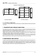
Example of installation in concrete and brickwork walls 


Summary of Contents for mcr PL1

Page 1: ... 08 GDAŃSK 2008 ul Grzegorza z Sanoka 2 80 408 Gdańsk tel 48 58 341 42 45 tel fax 0 58 341 39 85 TECHNICAL AND OPERATIONAL DOCUMENTATION Overpressure bleed damper of mcr PL1 type FIRE VENTILATION SYSTEMS DEPARTMENT ...

Page 2: ... THE DOCUMENTATION 3 3 PURPOSE OF THE DEVICE 3 4 CONSTRUCTION AND PRINCIPLE OF OPERATION OF THE DEVICE 3 5 DESIGNATION OF THE DEVICE 6 6 INSTALLATION OF THE DEVICE 6 6 1 PRE INSTALLATION INSPECTION 6 6 2 INSTALLATION OPENING 6 6 3 EMBEDDING 7 6 4 ELECTRICAL CONNECTIONS 8 7 TRANSPORT AND STORAGE CONDITIONS 8 8 MAINTENANCE AND SERVICE 8 9 TERMS OF GUARANTEE 9 ...

Page 3: ...r partition thus operating as so called safety valves that prevent the increase of pressure above a set value e g in a protected staircase The devices meet the requirements of the PN EN 12101 6 standard Fire Resistance ___________________________________________________________________ The device does not feature fire resistance as it is not required for its correct operation Execution Versions __...

Page 4: ...uitable flow of an air stream Driving and Tripping Systems ____________________________________________________ The driving system of mcr PL1 dampers is made of suitably selected steel weights that are mounted on blades of the device Dimensions _______________________________________________________________________ Mcr PL1 dampers are manufactured in the following dimensions Height Breadth B mm H ...

Page 5: ...ssembly sets are made of a suitable number of single dampers of the basic type as well as flat bars and connecting elements Basic dimensions of mcr PL1 dampers have been presented on the drawing below 3 2 4 1 Technical characteristics 50 55 60 65 70 75 80 85 90 4000 5000 6000 7000 8000 9000 10000 11000 12000 13000 discharge V m3 h pressure P Pa PL500x500 PL600x600 PL750x750 PL400x400 NOTE Net dime...

Page 6: ...TION INSPECTION __________________________________________ Each damper is inspected before packing and shipment by the manufacturer After unpacking at the recipient perform visual inspection to check if the casing has not been deformed and whether the damper has not been damaged during transport 6 2 INSTALLATION OPENING _________________________________________________ The minimum size of the open...

Page 7: ...mper with protective film or other covering material before installation until the masonry and finishing work is completed After the concrete mortar sets remove the brackets and open individual blades of the damper manually to check if they operate correctly Connection of the embedded damper to the ventilation duct must be executed coaxially During installation of the damper in the partition a dam...

Page 8: ...r each transport each damper should be visually inspected The damper must not be hit or dropped During handling and installation attention should be paid to the damper baffle The dampers should be stacked in no more than 2 layers vertically in closed rooms ensuring protection against external weather conditions In the case of storing of the dampers on the ground they should be placed on protective...

Page 9: ...ull value with no financial consequences to the purchaser 5 The guarantee does not include the operations performed by the purchaser user specified in the Documentation 6 The Manufacturer is absolved from the guarantee and any obligations resulting from the guarantee if a the product has mechanical damage created due to improper transport or unloading using own means of the purchaser improper inst...

Reviews: