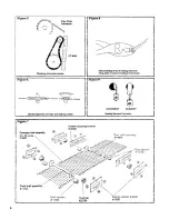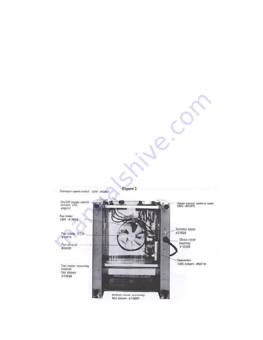
C Conveyor Speed Control/
P.C. Board
(Figure 1 & 2)
1.
Remove bottom cover.
2.
Pull off speed control knob and remove the nut
securing the control board panel. Pull out the
control from the back of the control panel.
3.
Cut the wire harness tie and disconnect the 2
wire leads at the wire connectors.
4.
Reverse this procedure to install the new
assembly.
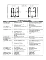
D Heater Control Switches
(Figure 1 & 2)
1.
Remove bottom cover.
2.
Pull off heater control knob to gain access to
the 2 slotted screws that secure the control to
the control panel. Remove these 2 screws.
3.
Disconnect the wires from the control terminal
ends.
4.
Install the new control securing with the 2
slotted screws.
5.
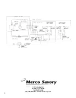
Re-attach wires to the terminal ends. (Refer to
the wiring diagram)
E Fan/Fan Housing/Fan Motor
(Figure 2)
1.
Remove the bottom cover.
2.
Rotate Fan Blades which will expose 2 nuts securing
the fan housing to the motor. Remove these two nuts
to remove the housing.
3.
To remove the fan motor, but do NOT remove the 2
motor mounting bracket nuts,
s
lide the motor until
clearance is achieved.
4.
Cut the wire harness ties to gain access to the wire
connector. Disconnect the 2 wire leads from the
motor, one at the wire connector and one at the
terminal block.
5.
Insert the new motor into the motor mounting bracket
and tighten the 2 motor mounting brackets nuts.
6.
Re-attach the two wire leads, one at the wire connec-
tor and one at the terminal block. (Refer to wiring
diagram)
7.
Install fan housing and secure with the 2 nuts.
8.
IMPORTANT: BE SURE TO RE-TIE THE
WIRE HARNESS SO THAT THE WIRES DO
NOT BLOCK THE FAN FROM SPINNING
FREELY.
3


