
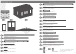


P 9
Please retain product label and instructions for future reference
15
15
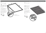
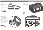
Step 13
Parts needed - No. 21 QTY 4
Ensuring the roof boards are
flush at the overhanging side
and meet at the apex, fix the
Eaves Frames (
No. 21
) to the
underside of the roof boards
using 9x40mm screws as shown
in the illustration.
*Please Note:
This image is for
illustrative purposes and may
differ from your choice in
product. Nevertheless the
process of fixing the eaves
frames is the same.
36x40mm Screws
40mm
screw
Pre drill
hole
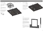
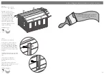
Step 14
Parts needed - No. 15 QTY 38
Place the first Floor Board (
No. 15
)
inside the building flush to the log
board on one side. Continue adding
the floor boards (
internally
) making
sure to interlock each individual
board.
*Do
NOT
secure the boards until
the last board has been measured
and cut.
Following the same method outlined
previously measure the gap between
the bottom of the tongue (
on the last
board placed
) and the log board.
Using a straight edge mark out the
measurement onto the last floor
board (
No. 15
) and cut along the
length removing the excess.
**Please note:
Mark the final board
2mm under the measurement; This
will allow the timber to expand and
contract correctly.
Once all the floor boards are in
position secure each board into
position using 8x40mm screws.
***Please Note:
Ensure to screw
through each of the floor boards
into the floor bearers.
304x40mm Screws
40mm
screw
Pre drill
hole
*
Cut to fit
28
21


