22318.37.01 15.09.05
9
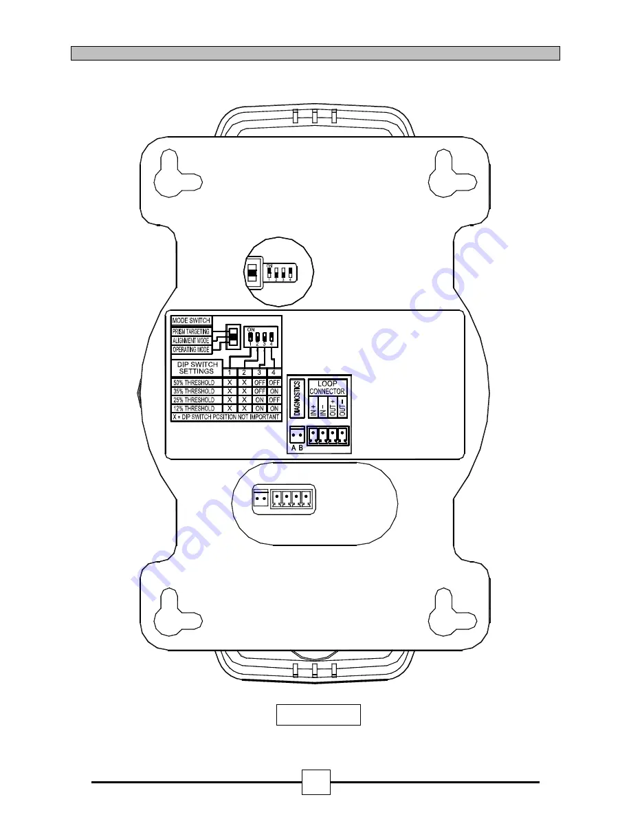
9. Detector Interface Assembly Configuration Settings.
Fig. 4.
www.acornfiresecurity.com
Page 1: ...100 Metres Unique simple alignment Loop powered Selectable alarm thresholds Low current consumption Automatic contamination compensation MAB50R MAB100R Reflective Beam Detectors Addressable 22318 37 0...
Page 2: ...tion page 4 5 5 Prism Targeting page 5 6 Alignment page 5 to 7 7 System Testing page 7 8 Connection and configuration Settings page 8 9 Detector Back View page 9 10 Beam Clearance page 10 11 Technical...
Page 3: ...of the Detector The fault condition will reset within 5 seconds of the condition being rectified The Detector monitors long term degradation of signal strength caused by component ageing or build up o...
Page 4: ...2 the lateral beam distance covered can be increased in relation to the angle of pitch up to a maximum of 25 For Example If the pitch angle is 20 degrees the lateral coverage can be increased from 7...
Page 5: ...r before installation this is only to prevent the cover becoming dislodged during handling Do not mount on plasterboard or cladded walls as these surfaces do and will move Determine the position of th...
Page 6: ...adjustment thumb wheels on two sides of the Detector positioned just behind the Detector Head cover Adjustment is achievable in both axes 6 1 Enabling Alignment Mode Do not remove the detector from t...
Page 7: ...ode and enter the Operating Mode LED flashing Slowly adjust a thumbwheel in one direction and observe the LED s LED flashing For optimum alignment deflection of the beam in all four planes should caus...
Page 8: ...fault 35 Select obscuration mark on filter to correspond with the Detector alarm threshold see fig 3 Place the filter over the receiver optics Top of Detector Head opposite end to the status indicatio...
Page 9: ...configuration settings is through the back plate of the Detector Head See Fig 4 The 4 way DIP is used to select the beams sensitivity 8 3 Typical Single Zone Wiring MAB50R MAB100R Connections Fire Pa...
Page 10: ...22318 37 01 15 09 05 9 9 Detector Interface Assembly Configuration Settings Fig 4 www acornfiresecurity com www acornfiresecurity com...
Page 11: ...re should be at least 0 5m diameter clearance down the entire beam path If there are highly reflective objects within 1 metre diameter of the beam path for the first 20 metres of the beam path for the...
Page 12: ...urrent into direct short circuit isolator open 13mA max Parallel Fault Resistance to be seen at the Control Panel for isolators to open 200 typ 12 Service Application Notes For full compliance with BS...