


ELECTRICAL ADJUSTMENTS
2-13: BRIGHT CENT
1.
2.
3.
4.
5.
6.
Receive the monoscope pattern. (RF Input)
Using the remote control, set the brightness and contrast
to normal position.
Activate the adjustment mode display of Fig. 1-1 and
press the channel button (13) on the remote control to
select "BRI CENT".
Press the VOL. UP/DOWN button on the remote control
until the white 10% is starting to be visible.
Receive the monoscope pattern. (Audio Video Input)
Press the TV/VIDEO button on the remote control to set
to the AV mode. Then perform the above adjustments
2~4.
2-14: COLOR CENT
1.
2.
3.
4.
5.
6.
7.
8.
Receive the color bar pattern. (RF Input)
Using the remote control, set the brightness, contrast,
color and tint to normal position.
Connect the oscilloscope to TP022.
Activate the adjustment mode display of Fig. 1-1 and
press the channel button (19) on the remote control to
select "COLOR CENT".
Adjust the VOLTS RANGE VARIABLE knob of the
oscilloscope until the range between white 100% and
0% is set to 4 scales on the screen of the oscilloscope.
Press the VOL. UP/DOWN button on the remote control
until the red color level is adjusted to 120
±
5% of the
white level. (Refer to Fig. 2-3)
Receive the video color bar pattern. (Audio Video Input)
Set to the AV mode. Then perform the above
adjustments 2~6.
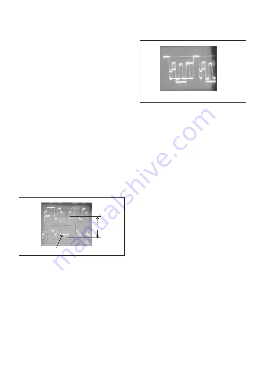
Fig. 2-3
120%
white 100%
2-15: TINT
1.
2.
3.
4.
5.
6.
7.
Receive the color bar pattern. (RF Input)
Using the remote control, set the brightness, contrast,
color and tint to normal position.
Connect the oscilloscope to TP024.
Activate the adjustment mode display of Fig. 1-1 and
press the channel button (22) on the remote control to
select "TINT".
Press the VOL. UP/DOWN button on the remote control
until the section "A" becomes as straight line.
(Refer to Fig. 2-4)
Receive the video color bar pattern. (Audio Video Input)
Set to the AV mode. Then perform the above adjustments
2~5.
Fig. 2-4
2-16: HORIZONTAL SIZE
1.
2.
3.
Receive the monoscope pattern.
Using the remote control, set the brightness and
contrast to normal position.
Adjust the VR404 until the SHIFT quantity of the
OVER SCAN on the right and left becomes 10
±
4%.
2-17: PALABOLA CORR
1.
2.
3.
Receive the chosshatch pattern.
Using the remote control, set the brightness and
contrast to normal position.
Adjust the VR403, so that the 4th length line becomes
straight from the outside of the right and left.
Please check if the fixed values of the each adjustment
items are set correctly referring below.
2-18: Confirmation of Fixed Value (step No.)
NO.
04
07
14
15
16
18
20
21
23
24
FUNCTION
H VCO
V.SHIFT
BRIGHT MAX
BRIGHT MIN
CONT CENT
CONT MIN
COLOR MAX
COLOR MIN
SHARPNESS
FM LEVEL
RF
04
02
130
60
35
25
75
00
45
01
AV
04
02
130
60
35
25
75
00
45
01
“A”
D-3


