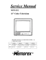


- 7 -
SOUND IF ADJUSTMENT
1. Connect TV Test Pattern Generator (NTSC signal, 70dB u , channel 2) to EXT. Antenna Terminal
(TE1) through TV Channel Signal Generator. (Standard modulation is 400Hz at 25kHz deviation for
sound signal.
2. Connect positive lead of DC Digital Voltmeter to TP7 and negative lead to TP4.
3. Adjust T203 so that the DC Digital Voltmeter reading is 4.0V.
COLOR PURITY ADJUSTMENT
For best results, it is recommended that the purity adjustment be made in the final receiver location. If
the receiver will be moved, perform this adjustment with it facing East.
The receiver must have been operating 15 minutes prior to this procedure and the face plate of the CRT
must be at room temperature. The following procedure is recommended while using a Dot/Bar
Generator.
1. Check correct location of all neck components. ( Refer to Figure 3 )
2. Rough -in the static convergence at the center of the CRT, as explained in the static convergence
procedure.
3.
Set the Contrast control to minimum position and Brightness control as far maximum as possible
without causing the picture to “bloom”.
4. Apply green raster signal from Dot/Bar Generator to receiver.
5. Loosen the deflection yoke clamp screw and pull the deflection yoke toward the rear of the CRT.
6. Begin the following adjustment with the tabs on the round purity magnet rings set together. Slowly
separate the two tabs while at the same time rotating them to adjust for a uniform green vertical
band at the center of the CRT screen.
7. Carefully slide the deflection yoke forward to achieve green purity (Uniform green screen).
NOTE:
Center purity is obtained by adjusting the tabs on the round purity magnet rings. Outer edge
purity is obtained by sliding the deflection yoke forward.
8. Check for red and blue field purity by applying red and blue raster signal alternately from Dot/Bar
Generator to receiver. Repeat steps 2 through 7, if required.
9. Tighten deflection yoke clamp screw.
10. Perform BLACK AND WHITE ADJUSTMENT procedure.
( CW : clockwise, CCW : counterclockwise )
FIG. 3
Summary of Contents for MT-1132
Page 5: ...REMOTE CONTROL LAYOUT 4 V I D E O V I D E O VIDEO...
Page 16: ...WIRING DIAGRAM 15...
Page 17: ...16 SCHEMATIC DIAGRAM MCT5315 S M p15 18 28 3 01 12 10 pm 17...
Page 19: ...EXPLODED VIEW 18 180 179 158...
Page 26: ......