background image

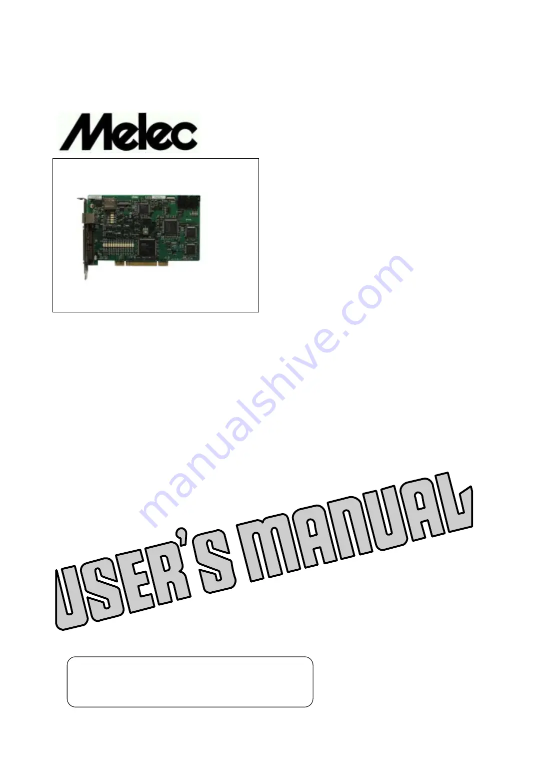
 Stepping & Servo Motor Controller

C-VX875

Instructions Manual

(For designers' use)

MN0203

  Please ensure to read and understand this
  Instructions Manual before using the Product.
  Please keep this Instructions Manual at hand
  so that it is always available for reference.

Summary of Contents for C-VX875

Page 1: ...r C VX875 Instructions Manual For designers use MN0203 Please ensure to read and understand this Instructions Manual before using the Product Please keep this Instructions Manual at hand so that it is always available for reference ...

Page 2: ...for the last equipment or a system according to a user s responsibility This product is designed and manufactured as a general industrial oriented general purpose product Therefore please do not use aircraft instruments an aerospace instrument a submarine relay appliance a nuclear control system transport plane machines vehicles a vessel etc the signal machine for traffic disaster prevention crime...

Page 3: ... or physical damage if you do not perform the procedure correctly Before Use Set up the product before operating it Refer to Section 3 Setting This product is equipped with a LIMIT overtravel signal and an FSSTOP signal to prevent mechanical damage The initial values of these signals are set to ACTIVE OFF B contact Accordingly even in a system configuration in which the FSSTOP and LIMIT signals ar...

Page 4: ... setting of the AL Ⅱ I O seiries 22 2 Baud rate setting of the AL Ⅱ I O seiries 22 3 Retry number setting of the AL Ⅱ I O seiries 22 3 4 Setting of Extend communications 22 4 CONNECTION 4 1 Example of user I O Interface Power Supply Connection 23 4 2 Examples of Connection to Drivers 24 1 Example of connection to the stepping motor driver 24 2 Example of connection to the servo motor driver 25 4 3...

Page 5: ... bit pulse differential counter the C VX875 has a variety of application such as counting feedback pulses from the servo driver detecting step out of the stepping motor with an encoder The applications also include interrupt output and external signal output using the comparator function of each counter After the command being executed is finished the commands stored in the reservation register ar...

Page 6: ... control block The drive control block outputs serial pulses to the motor driver The 2 axis indicated by is interrelation It enables 2 axis linear interpolation or 2 axis circular interpolation Counter block The counter block has three types of counters ADDRESS COUNTER PULSE COUNTER and DFL COUNTER Can use as hard timer ADDRESS COUNTER PULSE COUNTER has 32 bit counter DFL COUNTER has 16 bit counte...

Page 7: ...user I O block interfaces with motor drivers sensors and general purpose I O equipment signals Special purpose I O block Applied Function The block interfaces with input signals what motors can be operated manually and what can output status signals to the outside AL Ⅱ I O Communication Control block It is the circuit block which controls AL Ⅱ I O communication The interface part of AL Ⅱ I O commu...

Page 8: ...side by status signal of each axis A general purpose standard MIL connector is used S1 Rotary switch that is set so that PCI can recognize the board number If two or more boards are inserted into the PC simultaneously set the switch properly so that every board number is unique RDY LED LEDs that allows the user to simply monitor the X Y Z and A axes to check whether the axes are operating normally...

Page 9: ...rrosive and flammable gasses and not affected by oil mist dust salt iron powder water and chemicals Not subject to constant vibration or excessive shock Not affected by electromagnetic noise caused by power equipment Free of radioactive materials and magnetic fields and not in vacuum 5 Dimensions Short card size 107mm 170mm 17mm 6 Weight About 0 2 kg 2 2 PCI Specifications No Item Specifications 1...

Page 10: ...ut until the specified pulses Pulses are continuously output until a stop command is detected function SCAN drive INDEX drive Pulses are output until the specified relative or absolute address is reached ORIGIN drive The specified drive processes are performed This drive is finished when the ORG signal specified edge is detected 2 axis linear Linear interpolation is performed toward the specified ...

Page 11: ... output pulses Pulse counter 32 bit counter that countes external pulse signals or encoder feedback pulses Pulse differential 16 bit counter that detects differences in the number of counter pulses by counting external pulse signals and encoder feedback pulses It can also be used as a 16 bit timer Comparator function Detection of a match of the three comparators of each counter Upon detection of a...

Page 12: ...terpolation drive specified coordinates from the current coordinates on the circular curve INDEX drive controll This function is allowed to set OFFSET of the start the start point at auto point at auto deceleration This function can be used deceleration When INDEX drive liner interpolation INDEX drive and circular interpolation INDEX drive MANUAL SCAN drive MANUAL SCAN JOG drive in the or directio...

Page 13: ...signal can be used as multipurpose sensor as follows SENSORx input signal SIGNAL INx input signal A status in any axis Status external signal The compare register value STATUS output signal output function of each counter can output as SIGNAL OUTx output signal Synchronized start You can perform synchronized start with any axis function A condition of start can be set by the condition as follows S...

Page 14: ...to evade the stagnation of the entire system by retrying it when the influence of the noise etc is given to AL Ⅱ I O communications The number of retrying is set by an Environment set function When retrying is made effective and the communication abnormality is detected retrying is automatically executed The setting of retrying is possible by the range from 0 non retry to 3 4 Initialize Auto trans...

Page 15: ...Logic switching is enabled for an input signal marked with Applied function Logic switching is enabled for general purpose input signal INx when this signal is used for DALM function Note 1 An external power supply is required for a signal that is photocoupler insulated The specified input voltage range is 24V 2V Current consumption at 24V is up to 200mA The initial values of the CWLM and CCWLM si...

Page 16: ...This signal is used for general This signal is used for general XDRST purpose output ZDRST purpose output 23 X axis positioning completion signal 73 Z axis positioning completion signal In In XDEND XPO X axis PO signal ZDEND ZPO Z axis PO signal 24 N C Reserved 74 N C Reserved 25 In XEA X axis encoder A phase signal 75 In ZEA Z axis encoder A phase signal 26 In XEA X axis encoder A phase signal 76...

Page 17: ...commended cable refer to the instruction manual of connection others Signal table No Signal name Description Direction 1 N C Connection is prohibited 2 N C Connection is prohibited side input output signal of the serial data 3 I O ALⅡ line driver positive logic 4 I V Power supply for AL Ⅱ I O communication 6 V 5 I V GND for AL Ⅱ I O communication 0 V side input output signal of the serial data 6 I...

Page 18: ... output status signals of any axes by setting status output function The initial values after the relevant signal is reset are as follows SIGNAL OUTn0 is CNTINT signal of Xn axis SIGNAL OUTn1 is CNTINT signal of Yn axis Note 4 When this bord is MANUAL mode SS0 SS1 input signal SEL A D enables general purpose sensor that MANUAL SCAN drive specified axis When general purpose sensor function is set a...

Page 19: ... circuits and external circuits Cutput specifications 3 Circuit Description Signal name DRST Can be connected from DRSTCCM to the 5V current limiting circuit up to 15 mA Interface 24V 24V voltage DRSTCCM Nch transistor 1 65KΩ Max15mA Cutput method Cpen collector output Cutput CN 30mA Vce 1V or less DRST current 50mA Vce 2V or less Max30mA Photocoupler CFF 0 1mA or less EXTVGND Cutput 1ms or less P...

Page 20: ...gnal name EA EB ZCRG Connected to a line driver output circuit Interface Line receiver input 5V compliant with RS422 should be connected to an RS422 compliant line driver specifications Input terminating 220Ω 220Ω resistor Equivalent Response EA EB 5MHz to 26C32 Equivalent to 26C31 frequency ZCRG 100KHz 5V D GND Insulation Non insulated Common for all axes Applied function Input specifications 3 C...

Page 21: ... 21 C VX875 Instructions Manual 2 8 Outside Dimensions C VX875 MADE IN JAPAN The thickness of attachment lug is included The thickness of attachment lug is included ...

Page 22: ...Environment set function unlike the switch setting done with other slave units 1 Address setting of the AL Ⅱ I O series The C VX875 address is H 0 fixation And please set not to overlap the address of each slave I O unit 2 Baud rate setting of the AL Ⅱ I O series As for the AL Ⅱ I O communication baud rate 10 Mbps 50 m or 20 Mbps 30 m can be selected To transmission rate to set in C VX875 please s...

Page 23: ...the power supply used for the driver interface CCTx signal DRST signal use one prepared by the controller such as DRSTCCM For details refer to Section 4 2 Examples of Connection to Drivers Power may be supplied to the driver from a power supply different from the C VX875 such as by connecting to the CCTx or DRST signal of the servo driver or motor free MF signal of the stepping driver If so and po...

Page 24: ...put ALM 24VGND Stepping motor driver side 29 3 ZCRG C C 3 30 ZCRG C C 3 25 EA C C 3 26 EA C C 3 27 EB C C 3 28 EB C C 3 50 100 D GND C C Contoller side Relay unit etc 1 If the current limiting resistor on the driver side is less than 150Ω externally add resistor so that the total resistor value becomes 150Ω or more 2 When the input circuit uses a 24V interface the connection is as follows 21 DRSTC...

Page 25: ...CRG C C Z 3 25 EA C C A Line driver 3 26 EA C C A 3 27 EB C C B Line driver 3 28 EB C C B 3 50 100 D GND C C S G GND Relay unit etc Servo motor driver side Controller side 1 If the current limiting resistor on the driver side is less than 150 Ω externally add resistor so that the total resistor value becomes 150 Ω or more 2 When input circuit of the servo driver uses a 24V interface the connection...

Page 26: ...less NPN Type PM 54 PM 54 15mA or less NPN Type PM 64 PM 64 15mA or less NPN Type OMRON EE SX910R OMRON EE SX910R 15mA or less NPN Type Please contact us when you use sensors other than the above example large 35mA article of consumption current etc 2 Example of connection to a limit sensor X axis pin number are used in this example CCW direction CW direction Sensor that goes ON Sensor that goes O...

Page 27: ...oes OFF upon receipt of light O J1 14 EXTV 3 NORG 4 ORG Power supply for coupler 24V PS 29 ZORG 30 ZORG Controller side When using the origin sensor origin proximity signal CCW direction CW direction ORG sensor NORG sensor O O Sensor that goes OFF Sensor that goes OFF upon receipt of light upon receipt of light J1 14 EXTV 3 NORG 4 Power supply for coupler ORG 24V PS 29 ZORG 30 ZORG Controller side...

Page 28: ...nnect the Z phase to the line driver output circuit 30 ZORG Controller side When using the PO signal of stepping motor driver Circular disk with a slit CCW direction CW direction attached to the rotating shaft ORG sensor NORG sensor O O Sensor that goes ON Sensor that goes OFF upon receipt of light upon receipt of light Stepping motor driver PO R GND J1 14 EXTV 3 NORG 4 ORG 23 Power supply for cou...

Page 29: ...ce of the AL Ⅱ I O communications cable is the following range including the multidrop wiring The wiring distance of Extend I O doesn t relate to AL Ⅱ I O communication baud rate RATE The wiring distance of Extend I O from each slave is within 1 m L1 RATE Multi drop Terminator Terminator Build in Address Address Address Slave unit Address Address 0 1 2 3 4 L2 C VX875 Extend I O Extend I O Extend I...

Page 30: ...al check Check whether dust is deposited Installation Not loose Torque wrench Check whether the product is firmly secured 6kg cm state Not loose and removed Visual check Check whether connectors are completely inserted Not loose and removed Visual check Check whether cables are to be removed Appearance is normal Visual check Check whether connecting cables are to be broken 3 Replacement method If ...

Page 31: ... 31 C VX875 Instructions Manual The main parts which revised by this manual Parts Content None ...

Page 32: ...and Service TEL 042 664 5384 FAX 042 666 2031 URL http www melec inc com Melec Inc Control equipment marketing department 516 10 Higashiasakawa cho Hachioji shi Tokyo 193 0834 Japan This Operating Manual is subject to change without prior notice for the purpose of product improvement c1111 ...

Reviews: