


Connection / Operating Instructions
Connection
• Connect the RED wire to the positive(12V or 24V DC) power terminal which is energized with the
ignition key in the accessory position.
• Connect the BLACK wire to a suitable negative connection point on the vehicle.
• Connect the GREEN (video 1 trigger) wire to the switched power output terminal of the „R“ (reverse)
gear. Trigger is always in priority.
• If another camera (CAM 2) is used, the white wire can be used as a switching signal.
• Is at the GREEN and WHITE wire a voltage, so the reversing camera is displayed.
Before making the connection, disconnect the ground terminal of the car battery for avoiding
short circuits.
The plugs should fully inserted into the connectors or jacks. A loose connection may cause
malfuntioning of the unit.
Operating Instructions
When you turn the ignition key to the accessory or on position, the power is supplied and monitor is in
stand-by mode. Note the power of the monitor:
When you push the power switch on the off position, the monitor placed in off mode. The monitor is not
turned on until restart the ignition key or push the power switch in on position.
Cleaning and general maintenance
• If your vehicle has been parked in direct sun light resulting in a considerable rise in temperature
inside the vehicle, allow the unit to cool off before operating.
• Clean the unit with a slightly damp soft cloth. Use a mild household detergent. Never use strong
solvents such as thinner or benzine as they might damage the finish of the unit.
Cleaning
Unplug or power off mode before cleaning. Do not use liquid cleaners or aerosol cleaners. Use a damp
cloth for cleaning.
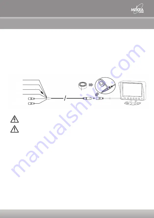
Power input lead (Green)
Power input lead (White) V2
Power input lead (Red) (DC IN)
Ground wire (Black)
Connect to CAM1
(V1 normal image)
Connect to CAM2
(V2 normal image)
Black 13 pin MALE to MONITOR
Surround vision for surround safety.


