background image

MEITRACK T366L

 User Guide                                                                                                 


Copyright ©  2020 Meitrack Group All rights reserved.                                                                                                - 11 - 

phone number to call the device. 

6.2


LED Indicator


Press and hold down the power button for 3

5 seconds to start the device. 

GPS Indicator (Blue) 

Blink (every 0.1 seconds) 

The device is being initialized or the battery power is low. 

Blink (0.1 seconds on and 2.9 seconds off) 

A GPS signal is received. 

Blink (1 second on and 2 seconds off) 

No GPS signal is received. 

GSM Indicator (Green) 

Steady on 

A call is coming in or a call is being made. 

Blink (every 0.1 seconds) 

The device is being initialized. 

Blink (0.1 seconds on and 2.9 seconds off) 

A base station signal is received. 

Blink (1 second on and 2 seconds off) 

No base station signal is received. 


6.3


Device Configuration


6.3.1


Installing the USB Driver


1.


Decompress  the 

stsw-stm32102.zip

  file  provided  by  Meitrack,  locate  the  following  file,  and  install  the  USB 

driver on a computer with 64-bit Windows system. 


2.


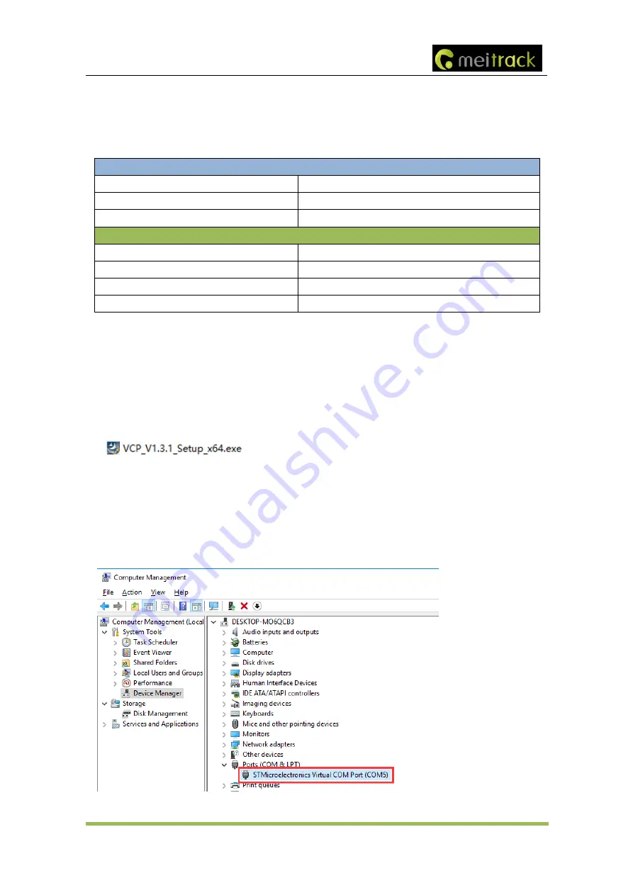
After  the  installation  is  finished,  connect  the  tracker  to  the  computer  by  USB  cable.  If 

STMicroelectronics 

Virtual  COM  Port  (COM5)

  is  displayed  on  the 

Computer  Management

  page,  the  driver  is  installed 

successfully. 

Note: Please power on the tracker and then connect the tracker to the computer by USB cable. Otherwise, 

Meitrack Manager will be unavailable. 


Summary of Contents for T366L

Page 1: ...MEITRACK T366L User Guide MEITRACK T366L User Guide...

Page 2: ...s reserved 2 Change History File Name MEITRACK T366L User Guide Project T366L Creation Date Update Date 20180509 20200313 Hardware Version H14 Software Version T366L_V066 or later Subproject User Guid...

Page 3: ...ications 8 4 T366L and Accessories 9 5 Appearance 10 6 First Use 10 6 1 Installing the SIM Card 10 6 2 LED Indicator 11 6 3 Device Configuration 11 6 3 1 Installing the USB Driver 11 6 3 2 Configuring...

Page 4: ...d to economic losses personal injuries and loss of assets and property caused by the use inability or illegality to use the product or documentation 2 Product Introduction The T366L is a vehicle GPS t...

Page 5: ...n be enabled by Meitrack Manager 2 1 3 Activating Output by Event You can activate output by event For example 1 When speeding is detected the device can control buzzer sounds 2 When unauthorized igni...

Page 6: ...theft alert by SMS or GPRS The buzzer will not stop buzzing until the arming state is disabled Set arming while moving Intercept moving vehicles When the stolen vehicle is moving you can set arming b...

Page 7: ...connected to the engine control cable through a relay 4 The RFID ignition function has been enabled by Meitrack Manager or MS03 tracking platform 5 The RFID event has been enabled on Meitrack Manager...

Page 8: ...he battery power is low a low power alert will be generated 3 2 Specifications Item Specifications Dimension 80 5 mm x 60 mm x 23 5 mm Weight 100g I O power cable length 50 cm Power supply DC 11 4 90...

Page 9: ...download card Optional accessories Optional Accessory Description Relay 12 V 24 V Connect to output 1 Buzzer Connect to the 1 Wire interface green cable which needs to be set to output 2 The buzzer sh...

Page 10: ...ck cover 2 Insert the SIM card into the card slot card chip facing down 3 Close the cover and tighten the screws Note Power off the device before installing the SIM card Ensure that the SIM card has s...

Page 11: ...device is being initialized Blink 0 1 seconds on and 2 9 seconds off A base station signal is received Blink 1 second on and 2 seconds off No base station signal is received 6 3 Device Configuration 6...

Page 12: ...nect the device to a computer by using the USB cable 3 Run Meitrack Manager then the following dialog box will appear 4 Turn on the device then Meitrack Manager will detect the device model automatica...

Page 13: ...es the date and time in MMDDYY hh mm format None V The GPS is invalid A Valid V Invalid 26 Indicates the GSM signal strength Value 1 32 The larger the value is the stronger the signal is If the value...

Page 14: ...OK Description Phone number A phone number has a maximum of 16 bytes If no phone numbers are set leave them blank Phone numbers are empty by default Phone number 1 2 3 Set these phone numbers to autho...

Page 15: ...the function will be unavailable Time indicates the consecutive time for the speed and alert time The parameter value ranges from 0 to 60000 Unit second Speed The parameter value ranges from 0 to 200...

Page 16: ...OK 6 5 6 Setting I O Port Status C08 SMS sending 0000 C08 IO0 Mn IO1 Mn IO2 Mn IO3 Mn IO4 Mn SMS reply IMEI C08 IO0 Mn IO1 Mn IO2 Mn IO3 Mn IO4 Mn Description 1 IO0 IO1 IO2 IO3 and IO4 indicate I O po...

Page 17: ...g System Visit http ms03 trackingmate com enter the user name and password and log in to the MS03 Purchase the login account from your provider For more information about how to add a tracker see the...

Page 18: ...or remote control input 4 Input 2 White Digital input positive trigger The port can be set to negative trigger or AD input 3 0 30 V Connect to the vehicle ACC cable by default to detect the vehicle AC...

Page 19: ...able Besides the above 8 pins there are the following 3 pins 9 GND 10 RS232 Tx 11 RS232 Rx Pin Number Color Description 9 GND Black Ground wire 10 RS232 Tx Purple The device sends data through RS232 p...

Page 20: ...lor Description Yellow Connect to 5 V power supply Black GND Green Remote control output cable Connect to input 1 grey cable which needs to be set to the remote control input Purple Cable for code mat...

Page 21: ...put 2 ACC or a towing event is triggered a vehicle theft alert event 58 will be generated by SMS or GPRS and the device will dial the authorized phone numbers in sequence Arming state Press once The b...

Reviews: