MEITRACK T311 User Guide
Copyright © 2014 Meitrack Group All rights reserved. - 14 -
6
Installing the T311
6.1
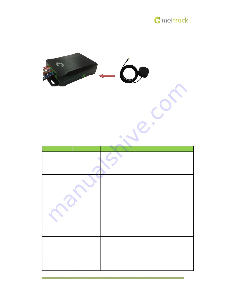
(Optional) Installing the GPS Antenna
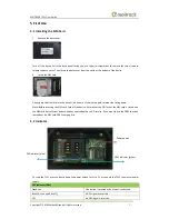
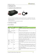
Connect the GPS antenna to the GPS port on the side panel of the tracker. It is recommended that the antenna
should face up to the sky and the antenna side with words should face downwards. Secure the antenna by
using double sided tapes.
Note: Do not install the GPS antenna at a place with metals.
6.2
Installing an I/O Cable
6.2.1
Port Definition
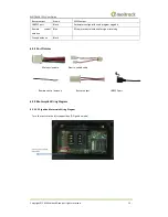
The I/O cable includes the power cable, positive and negative input, and output.
Port
Color
Description
Positive
power
supply
Red
Connected to the positive power supply 11–90V input with the 10 A
fuse.
Negative
power
supply (GND)
Black
Connected to the negative electrode.
Ignition start cable
Orange
Connected to the positive output line (that is, the ACC cable) of an
electronic door lock on an electric vehicle or motorcycle. Used to
detect whether the vehicle key switch is turned on or to output
positive electricity by simulating the original electronic door lock
when the vehicle is started remotely. The head of the positive
electricity on a motorcycle use the same type of cable as the
electronic door lock on an electric vehicle.
Upper
flameout
cable
Pink
Used for remote flameout (only for motorcycles. For details, see
the wiring diagram.)
Lower
flameout
cable
Grey
Used for motorcycle remote flameout and electric vehicle anti lock
motor.
Start
Blue
Used for remote start. Positive electricity is output upon the start. A
relay is connected to a negative start vehicle to change the positive
start line to a negative start line. (Only for motorcycles. For details,
refer to the wiring diagram.)
Motor pulse line
Green
Connected to the motor pulse signal cable. Used only for electric
vehicles.


