18
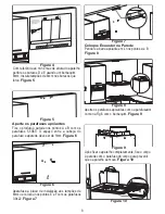
Drill the D, E points with a Ø 6mm drill bit to screw
the flue installation plate referring to the min. and
max. heights of the appliance.
Figure 5
Install 6 mm dowels to the holes you have drilled.
D
E
Figure 4
Figure 5
A
B
C
D
E
Tightening the suspension screws:
Tighten 5.5x60 suspension screws to Ø10 mm
dowels (A, B) you have tapped on the wall. The
distance between screw head and the wall shall be
5 mm.
Figure 6
Figure 6
D
E
D
E
Tighten the flue installation plate to the Ø 6 dowels
you have tapped to the wall using the 3.9x22 screw
supplied with your hood.
Figure 7
Suspending the Hood to the Wall:
Hold the hood from its body and suspend it to the
wall on A and B points using the (L) plates you have
fixed on the hood cabinet before.
Figure 8
Figure 7
Figure 8
Figure 9
When the suspension procedure is completed,
tighten the suspension screws installed to the wall in
Fig. 6
with a screwdriver to prevent moving of the
appliance.
Figure 9
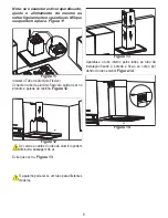
After you have fixed your hood completely, secure
the body with a screw from the hole (C) inside the
body to prevent it from moving.
Figure 10
Figure 10
Summary of Contents for MEP 191 XN
Page 2: ...2 DESENHOS TÉCNICOS ...
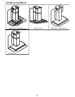
Page 13: ...13 TECHNICAL DRAWINGS ...


