background image

-7- 


MT-50

 Series 


2-2 

Assembling Steps


2-2-1

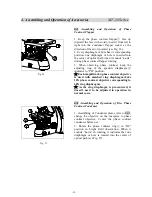
 Assemble the Condenser 

Assemble Koehler Illuminator Condenser 

1. Rotate the coarse focusing knob

  to raise the 

stage to the highest position (see Fig. 4). 

2.  Rotate  the  condenser  up-down  knob

  to 

lower  the  bracket  of  condenser  to  the  suitable 

position. 

3. Fully loosen the condenser lock-screw

4.  Insert  the  condenser  into  the  hole  of  stand 

according to the arrowhead, until the condenser is 

equal  with  the  stand,  and  then  rotate  the 

condenser to make the handle frontward. 

5.  Tighten  the  lock-screw

  of  condenser,  then 

raise the condenser with the up-down knob to the 

highest position. 


2-2-2


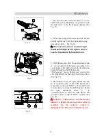
Assemble the Objective


1. Rotate the coarse focusing knob

  to lower the 

stage to a suitable position (see Fig. 5). 

2.  Install  the  objectives

  into  the  objective 

nosepiece

  from the lowest magnification to the 

highest in a clockwise direction from the rear. 

  When  operating,  first  use  the  low 

magnification  objective  (4X or  10X) to  search 

for specimen and focus, and then replace with 

high magnification objective to observe. 

  When  replacing  the  objective,  rotate  the 

objective nosepiece until it sounds “ka-da”, to 

make sure the objective wanted is in the center 

of optical path. 


2-2-3

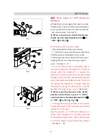
 Assemble the Eyepiece 

1. Take down the cover of eyepiece tube

2.  Insert  the  eyepiece

  into  the  eyepiece  tube, 

until it touches the surface (see Fig. 6). 

3. When adjusting diopter by adjustable eyepiece, 

lock  eyepiece  with  hexagon  lock-screw

  to 

avoid  the  eyepiece  group

  rotating  in  eyepiece 

tube, as the figure shows. 


Fig. 6


Fig. 5


Fig. 4


3


14


13


4


5


4


4


Summary of Contents for MT-50 Series

Page 1: ...ntenance about MT 50 series biological microscope Please study this manual thoroughly before operating and keep it with the instrument The manufacturer reserves the rights to the modifications by tech...

Page 2: ...e Diaphragm 12 3 10 Use the Oil Objective 100X 12 3 11 Use the Filter 13 3 12 Replace the Fuse 13 3 13 Assemble and Use of the TV Device 13 3 14 Assemble the Photography Device 14 4 Assembling and Ope...

Page 3: ...knob or head when moving 4 When working the surface of condenser will be very hot Make sure there is enough room for the heat dissipating around the condenser see Fig 2 5 Connect the microscope to the...

Page 4: ...lease use these chemical in a ventilated place 2 Don t use organic solution to wipe the surfaces of the other components Please use the neutral detergent if necessary 3 If the microscope is damped by...

Page 5: ...ries Objective Nosepiece Arm Tension Adjustment Ring Coarse Focusing Knob Fine Focusing Knob Light Adjustment Knob Koehler Illuminator Condenser Binocular Head Eyepiece Objective Stage Koehler Illumin...

Page 6: ...s Eyepiece Objective Stage Koehler Illuminator Condenser Light Source Coarse Focusing Knob Power Switch Fine Focusing Knob Focus Arm Arm Lock screw Trinocular head Objective Nosepiece Koehler Illumina...

Page 7: ...tor Filter Block Adjustment knob Light Shield Objective Stage Koehler Illuminator Condenser Koehler Illuminator Condenser Light Source Power Switch Coarse Focusing Knob Objective Nosepiece Arm Focus A...

Page 8: ...escence Illuminator Eyepiece Objective Nosepiece Arm Stage Fine Focusing Knob Coarse Focusing Knob Light Adjustment Knob Focus Arm Light Shield Objective Koehler Illuminator Condenser Koehler Illumina...

Page 9: ...lowing is the Assembling Scheme and the numbers denote the assembling order Before assembling make sure there is no dust or dirt Assemble carefully and do not scrap any part or touch the glass surface...

Page 10: ...6 MT 50 Series LED Fluorescence Microscope Light Source Power Cord LED Fluorescence Illuminator Binocular Head Eyepiece Light Shield Objective Condenser Transformer...

Page 11: ...oarse focusing knob to lower the stage to a suitable position see Fig 5 2 Install the objectives into the objective nosepiece from the lowest magnification to the highest in a clockwise direction from...

Page 12: ...LED light source s 2 2 5 Connect the Power Cord Don tuse strong force when the power cord is bended or twisted otherwise it will be damaged 1 Make sure the power switch is at 0 OFF before connecting...

Page 13: ...ace the Specimen Slide 1 Push the wrench of the specimen holder backwards 2 Loosen the wrench and clamp the slide by the clips while the cover glass faces up see Fig 10 3 Rotate the X and Y axis knob...

Page 14: ...ig 13 There is 5 diopter on the ring To align with the scale value is your eye s diopter Remember your eye s diopter so that you could use next time 3 6 Adjust the Interpupillary Distance When observe...

Page 15: ...e center of the field of view see Fig 17 6 Open the field diaphragm gradually If the image is in the center all the time and inscribed to the field of view it shows condenser has been centered correct...

Page 16: ...0 Use the Oil Objective 100X 1 Use objective 4X to focus the specimen 2 Place a drop of oil on the specimen see Fig 20 3 Rotate the nosepiece counterclockwise and rotate the oil objective 100X to the...

Page 17: ...see Fig 22 Specification of the fuse T250V 3 15A 3 13 Assemble and Use of the TV Device 1 Loosen the lock screw on the trinocular head and get down the dust cover of the trinocular see Fig 23 2 Get d...

Page 18: ...aphy device to the trinocular Screw on the lock screw see Fig 24 3 Loosen the lock screw on the photo tube and get down the photo tube see Fig 25 4 Insert the photography eyepiece 3 2X to the eyepiece...

Page 19: ...the aperture diaphragm indicator to PH position Each magnification phase contrast objective is used with matched ring diaphragm Like 10X phase contrast objective corresponding to 10X ring diaphragm As...

Page 20: ...center overlap the phase ring center see Fig 27 Fig 28 6 Adjust phase ring and halo of other magnification phase contrast objective according to above steps It can not get the phase contrast microscop...

Page 21: ...one side of USB data cable into USB output port on the back of observation head see Fig 31 View the microscope video with two eyes by the corresponding video capture and analysis software Digital USB...

Page 22: ...to the arrow pointed to switch between the transmission bright field and the LED fluorescence Flourescence means flourescence observation and Brightfield means bright field observation See Fig 35 6 I...

Page 23: ...power supplying The indicator is green in normal while the indicator is orange the indicator becomes green when the pack is fully charged At the same time the last bulb of the light strip 11 is red wh...

Page 24: ...have accumulated on the lens Clean the lens 4 Unclear image No cover glass on the specimen slide Add the cover glass The cover glass is not standard Use a standard cover glass with thickness 0 17mm Th...

Page 25: ...Tension knob is too tight Loosen a little 4 Stage declines itself Tension knob is too loose Tighten a little 5 Coarse focusing knob can t rise The limit stop knob is locked Loosen the knob 6 Coarse f...

Reviews: